





 Submit


How to Read TVS Diode Peak Pulse Power: Waveform, Temperature, and Pulse Width A 200 W, 600 W, or 1500 W rating on a TVS diode is peak pulse power under a defined waveform and starting temperature. It is not continuous power dissipation. PPPM must be read together with pulse width, waveform, peak pulse current, clamping voltage, and thermal derating. The same TVS can tolerate very different peak currents for a short, fast pulse and a longer surge. Unless the test conditions match, a 1500 W dev
 2026.08.05 00:00:00
 83
83





A 200 W, 600 W, or 1500 W rating on a TVS diode is peak pulse power under a defined waveform and starting temperature. It is not continuous power dissipation. PPPM must be read together with pulse width, waveform, peak pulse current, clamping voltage, and thermal derating.
The same TVS can tolerate very different peak currents for a short, fast pulse and a longer surge. Unless the test conditions match, a 1500 W device cannot simply be described as 2.5 times stronger than a 600 W device.
What does PPPM mean?
PPPM is peak pulse power. At the stated test point, it can be checked approximately by multiplying the clamping voltage by the peak pulse current:
PPPM ≈ VC × IPP
VC is the maximum clamping voltage at the specified peak pulse current. IPP is the associated peak current. The two values must come from the same test condition. Do not multiply the VC of one part by the IPP of another, and do not replace VC with breakdown voltage.
VBR identifies the breakdown range where avalanche conduction begins. As current rises, the voltage across the TVS rises above VBR. The downstream circuit therefore has to be checked against VC at the relevant current, plus any overshoot caused by PCB parasitic inductance.
How do 200 W, 400 W, 600 W, and 1500 W devices compare?
Holding the working voltage constant makes the relationship easier to see. The following unidirectional ASIM devices all have a 5 V VRWM, a 6.4 to 7.0 V breakdown range, and a maximum VC of 9.2 V, but their packages and pulse-current ratings differ:
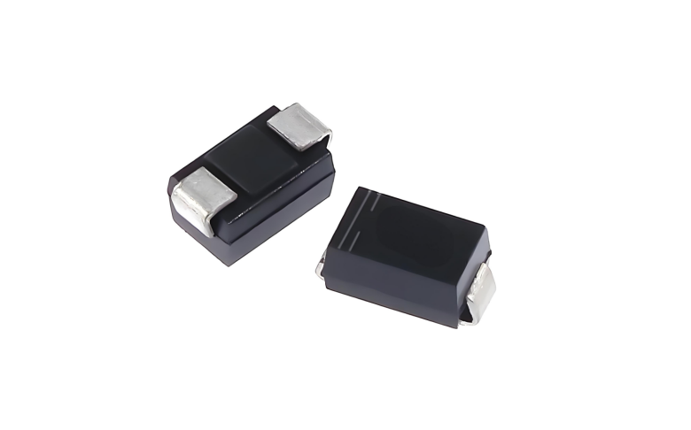
SODA5.0V-SH uses an SOD-123FL package. PPPM is 200 W and IPP is 21.74 A.
SMA04J05V uses an SMA package. PPPM is 400 W and IPP is 43.5 A.
SMB06J05V uses an SMB package. PPPM is 600 W and IPP is 65.3 A.
SMC15J5.0V uses an SMC package. PPPM is 1500 W and IPP is 163 A.
For the SMA04J05V, 9.2 V multiplied by 43.5 A is approximately 400 W. For the SMB06J05V, 9.2 V multiplied by 65.3 A is approximately 600 W. The arithmetic confirms that PPPM, VC, and IPP belong to the same rated operating point.
It does not prove that these currents are valid for every surge. The specified waveform and temperature still control the rating. If the application uses a different pulse shape, consult the appropriate pulse-power curve, current curve, or energy limit for that condition.
Why does pulse width change the allowable current?
During a surge, the TVS converts electrical energy into heat. A wider pulse generally deposits more energy and gives heat more time to spread through the die and package. At the same peak current, a 1000 µs pulse usually produces a heavier thermal load than a 20 µs pulse.
For that reason, a rating based on a 10/1000 µs waveform cannot be transferred directly to an 8/20 µs surge, an automotive load-dump event, or repetitive inductive switching. Rise time, time to half value, source impedance, and repetition rate all matter.
Energy deserves its own check. Two pulses can have the same peak voltage but very different duration and absorbed energy. Longer events require a review of transient thermal behavior and pulse derating, not just the headline wattage.
How does temperature reduce the power margin?
Peak pulse ratings are specified at a defined initial junction or ambient condition. In a hot enclosure, or next to a power component, the TVS begins the event at a higher junction temperature. Less thermal headroom remains.
Use the temperature derating curve for the actual operating condition. A room-temperature surge pass does not establish the result at maximum load and maximum ambient temperature. Copper area, pad geometry, and the path into the PCB also affect the real temperature rise.
Repetitive pulses can accumulate heat. A single event may be harmless when there is time to cool, while a train of pulses raises average temperature until leakage shifts or the junction fails. Repetitive or sustained overvoltage may require current limiting, a fuse, an electronic disconnect, or a multi-stage protection network.
What is a practical TVS selection sequence?
Start with maximum continuous voltage
Determine the highest normal voltage, including tolerance, charging state, ripple, and steady overvoltage. VRWM must keep the TVS off during normal operation. The system label, such as 12 V or 24 V, is not enough.
Estimate the current through the TVS
Use the surge open-circuit voltage, source impedance, line resistance, and TVS clamp characteristic. The current is not simply open-circuit voltage divided by source resistance because VC and upstream impedance affect the result.
Compare VC with downstream tolerance
Read VC near the estimated current, then include PCB inductive overshoot. Compare the result with the transient tolerance of the downstream MOSFET, power IC, and capacitors. A high PPPM does not help if the clamp voltage is already above the circuit limit.
Apply temperature and repetition derating
Check ambient temperature, starting junction temperature, pulse count, interval, and service-life requirement. ASIM offers 200 W through 1500 W families in different packages, but final selection must compare parts under a common waveform and thermal condition.
Can PCB layout change the residual voltage?
Yes. The traces from the connector to the TVS and from the TVS to the return path have parasitic inductance. The faster the surge edge, the more voltage this inductance adds. A measurement at the downstream circuit can be higher than the VC listed for the component itself.
Place the TVS close to the surge entry point. Keep the discharge branch short and wide, and keep the return current away from sensitive circuits. Route the input through the protection node before it reaches the load. A TVS connected through a long side branch starts clamping after the surge has already travelled farther into the board.
A larger package still needs appropriate pads and copper. Replacing an SMA part with an SMC part while retaining a narrow trace and distant ground does not convert the larger die into effective system protection.
Common questions about TVS peak pulse power
Can a 1500 W TVS dissipate 1500 W continuously?
No. The value is a short-duration peak pulse rating under specified conditions. Sustained overvoltage requires current limiting, disconnect, or fuse coordination.
Can two 600 W TVS diodes be swapped directly?
Not without checking VRWM, VBR, VC at the stated IPP, waveform, polarity, leakage, package, and temperature derating. Equal power ratings cover only one part of the design.
Does a higher power rating always mean a lower clamp voltage?
No. VC depends on voltage grade, die structure, dynamic resistance, and pulse current. Compare concrete part numbers at similar current, waveform, and temperature.
Can a large TVS be selected before the surge waveform is known?
A larger footprint can be reserved for prototypes, but the design cannot be approved. Without waveform and source impedance, the TVS current, absorbed energy, and junction heating remain unknown.
Before releasing the part, document maximum continuous voltage, surge waveform, source impedance, expected IPP, VC at that current, downstream voltage limit, temperature, and repetition rate. Peak pulse power is one column in that review, not the whole decision.
 Previous

Related News

2024.10.12
EMC testing Contents and Current Situation of Automotive Electronic products

2025.02.21
How to choose the best circuit protection devices in a circuit?
2026.07.20
How should a failure in the CAN communication surge test be handled?
2026.07.23
How to Select Low-Capacitance ESD Protection for MIPI D-PHY Interfaces: Key Design Considerations for Camera and Display Links

2026.07.24
What are the differences between SMA, SMB, and SMC packaged TVS diodes? Selection based on power and size.
2026.07.29
How can system crashes, resets, or communication interruptions caused by ESD be remedied? Pinpoint sensitive areas based on the failure symptoms.
2026.07.29
Why does the ESD test still fail after replacing the protection device? Troubleshooting discharge paths, grounding, and component placement.
2026.08.04
How do you remediate an ESD test failure for a device with a metal enclosure? Troubleshooting chassis grounding, gaps, and shielding connections.

2026.08.05
How to Read TVS Diode Reverse Leakage Current (IR): Temperature, VRWM, and Standby Power

2026.08.05
How to Read IEC 61000-4-2 Ratings for ESD Diodes: Component Rating vs System Compliance


