





 Submit


ESD Arrays vs Single-Channel Diodes
 2026.08.11 00:00:00
 73
73





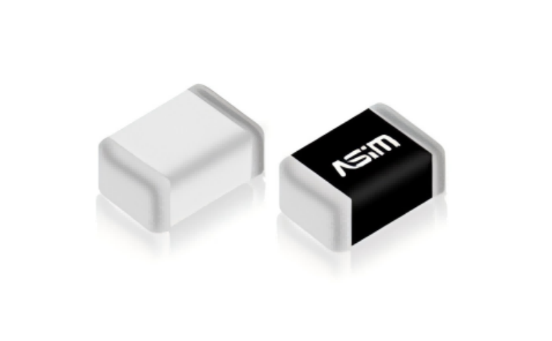
The ASIM ESD5X004SA is a four-channel bidirectional array with 5 V VRWM, 0.25 pF typical capacitance, and 12 V maximum VC at 6 A.
The numbers are useful only with their stated current, waveform, temperature, frequency, and package conditions. A product selection begins with the actual electrical window and ends with board-level verification. It does not end with one favorable catalog value.
How should the comparison be read?
Start with normal operating voltage and the allowed fault condition. Then compare the maximum clamp voltage or impedance at the relevant test point. Check the package, return path, and channel structure before treating either part as a candidate. This sequence prevents a common error: choosing a device for one excellent number while ignoring the condition that made the number possible.
What changes on a real PCB?
Pads, traces, vias, cable position, and return inductance all change the result at the protected pin. A low-capacitance part on a long branch can still load a high-speed channel. A low clamp rating can still leave the IC with excess voltage if the return path is long. Use the real layout and measure both device terminals and the downstream node when margin is limited.
A practical verification sequence
Freeze sample, load, cable, and operating mode.
Test one part or one layout change at a time.
Record waveforms, current path, function, leakage, and reset or error status.
Restore the original configuration and repeat the test to confirm the change caused the result.
Common questions
Is the part with the lower published value always better?
No. Values must be compared at the same condition and against the actual system requirement.
Can package style decide the selection?
No. Package affects parasitics and assembly, but voltage window, clamp behavior, topology, and layout must also fit.
Why can a catalog-matched device fail in a product?
The full current path includes the enclosure, connector, cable, PCB, and protected circuit. Board-level validation is required.
When an ESD array is the right tradeoff
An ESD array reduces placement count when several external lines have comparable electrical requirements. It does not remove the need to assess each line. ASIM ESD5X004SA is a four-channel bidirectional array with 5 V VRWM, 0.25 pF typical capacitance per channel, 6 A IPP, and 12 V maximum VC at its listed condition. ESD5E001TA is a single-channel bidirectional part with 5 V VRWM and 0.08 pF typical capacitance. The difference in channel count is only the start of the review.
Use an array when the lines share a compatible voltage window, protection polarity, bandwidth allowance, and physical entry point. Typical candidates include grouped low-speed control lines. A single-channel part gives more freedom when one line has a tighter capacitance budget, a different reference arrangement, or a different failure consequence. Mixed interfaces deserve special care: a connector carrying a high-speed differential pair, a reset line, and several GPIOs is not automatically an array application.
The shared structure changes fault review. Verify whether the array has a common return arrangement, how the layout connects that return to the reference plane, and what happens if one line sees an abnormal voltage while the others are active. The device data sheet describes the part; the board determines how fast current reaches the return and how much coupling the branch adds to neighboring traces.
Place the array close to the connector, with protected traces leaving directly toward the circuit. Do not create long stubs merely to reach a convenient component row. For paired signals, mirror pad exits and via patterns. For separate control lines, keep noisy discharge current away from reset, oscillator, and analog-reference paths. A small package can make this harder because the return pads, signal pads, and breakout traces compete for the same area.
Review the array decision with a line-by-line checklist:
highest normal voltage and polarity of every protected conductor;
capacitance and leakage allowance for each channel;
whether all channels enter the board at the same physical location;
return-pad connection and distance to the intended reference;
isolation consequences if one external line is miswired or stressed;
signal and function results after repeated test events.
An array is a packaging choice plus an electrical topology choice. Select it only after every included line passes the same board-level review. If one channel does not fit, split the protection scheme rather than accepting a compromised interface.
Validation evidence for the release record
Use a fixed test configuration before comparing candidates. The record should name the sample revision, cable type and length, supply setting, load state, firmware version, ambient condition, and measurement point. Record the original waveform before changing the device or layout. Change one variable, repeat the same test, restore the original configuration, and repeat it again. This A/B/A sequence is more useful than a single improved screenshot because it exposes changes caused by cable movement, probe placement, or operating state.
Keep electrical evidence and functional evidence together. Electrical evidence includes the voltage at the entry and the protected pin, current where appropriate, and the exact pulse or discharge condition. Functional evidence includes communication errors, reset events, leakage, standby current, temperature, and recovery after repeated stress. A passed bench pulse does not close the review if normal operation is degraded. Conversely, a clean function test without the relevant electrical condition does not prove clamp margin.
The approved part number therefore belongs with a specific footprint and layout revision. If either the footprint, return path, cable arrangement, or downstream circuit changes, reopen the comparison and verify the affected condition again.
The final record should connect the selected model, its conditions, its PCB location, and the verification result.
 Previous

Related News

2024.10.12
EMC testing Contents and Current Situation of Automotive Electronic products
2026.07.23
How to Select Low-Capacitance ESD Protection for MIPI D-PHY Interfaces: Key Design Considerations for Camera and Display Links
2026.07.25
Why Must Pulse Waveforms Be Considered When Selecting TVS Diodes for Automotive Electronics? Key Points for ISO 7637 Applications
2026.08.04
How to implement ESD remediation for devices with plastic housings? Design considerations for buttons, cutouts, and internal PCB dimensions.
2026.08.05
How to Read TVS Diode Peak Pulse Power: Waveform, Temperature, and Pulse Width A 200 W, 600 W, or 1500 W rating on a TVS diode is peak pulse power under a defined waveform and starting temperature. It is not continuous power dissipation. PPPM must be read together with pulse width, waveform, peak pulse current, clamping voltage, and thermal derating. The same TVS can tolerate very different peak currents for a short, fast pulse and a longer surge. Unless the test conditions match, a 1500 W dev
2026.08.06
How to Read ESD Diode Capacitance for High-Speed Interfaces


