Submit






Evaluating a TVS diode manufacturer begins by checking whether VRWM, VBR, VC, and IPP are tied to clear test conditions. A claim such as low clamping or high power has little design value without pulse waveform, current, temperature, and package information. The power input's highest continuous voltage, downstream limit, surge source impedance, and PCB overshoot must be reviewed with the supplier data.
Compare complete pulse conditions instead of wattage labels
Peak pulse power depends on waveform, pulse width, and starting temperature. Two suppliers can publish the same 400 W label while using different series definitions or supporting information. The same SMA package name does not prove equal die size, dynamic resistance, thermal path, breakdown spread, or clamping performance.
Place these fields on one supplier-comparison line:
reverse working voltage and the permitted continuous operating boundary;
breakdown range and breakdown test current;
clamp voltage, peak current, and pulse waveform;
leakage current with reverse voltage and temperature;
peak pulse power, derating information, and mounting condition;
unidirectional or bidirectional construction;
package dimensions, land pattern, marking, and lot code.
Reject a comparison that detaches VC from IPP. A lower clamp number measured at a much lower current does not prove better protection. The same rule applies to breakdown voltage and leakage.
Define the power-system window before requesting samples
A 24 V adapter does not automatically require a 24 V VRWM device. Measure the adapter's positive tolerance, no-load output, startup, hot-plug behavior, and any sustained charging or fault state at the PCB. The TVS must remain compatible with valid continuous operation across temperature.
Then analyze the surge path. Source impedance, upstream resistance, cable inductance, and other protection elements determine how much current reaches the TVS. The device clamp plus PCB overshoot must remain below the allowed voltage of the DC/DC converter, MOSFET, input capacitor, and monitoring circuitry.
Prepare the sample request in this order:
Record maximum continuous board voltage and temperature range.
Identify the required surge waveform, source impedance, repetition, and coupling path.
Calculate the downstream maximum residual-voltage boundary.
Ask each manufacturer for a model whose published conditions cover the request.
Test leakage, temperature, startup, shutdown, and hot plug on the same input board.
Apply the defined transient and measure both TVS terminals and the sensitive downstream node.
Inspect leakage, function, appearance, and temperature behavior after stress.
This sequence prevents the supplier evaluation from becoming a contest over the largest printed wattage.
Use SMA04J24V as a traceable parameter example
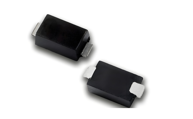
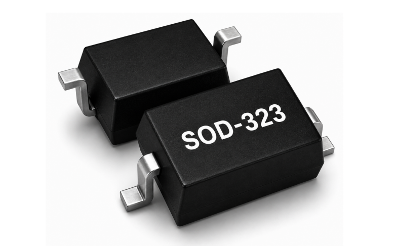
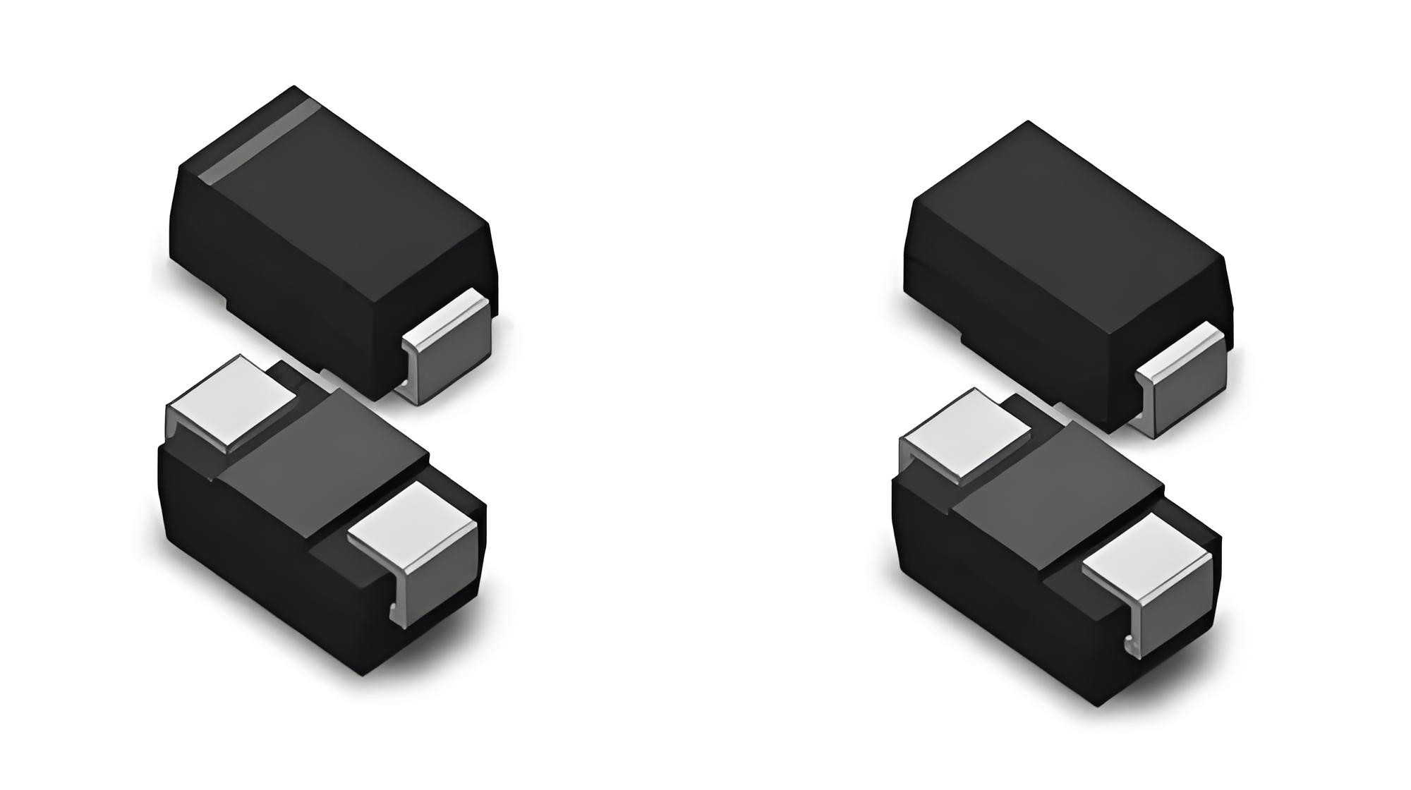
ASIM SMA04J24V uses an SMA/DO-214AC package. Its verified headline values are 400 W peak pulse power, 24 V reverse working voltage, a 26.7 V to 29.5 V breakdown range, 10.3 A peak pulse current, 38.9 V maximum clamp voltage at the stated condition, and 1 microampere reverse leakage under the specified test condition.
This parameter set can enter a 24 V-class screening table because the voltage, current, clamp, and package are identifiable. It still does not prove suitability for every 24 V input. The design team must confirm the continuous high-line margin, actual surge current, downstream voltage tolerance, pulse energy, repetition, and PCB thermal path.
If another manufacturer provides only 24 V, 400 W without a breakdown range, clamp condition, or leakage test point, the two devices are not ready for an alternate-source decision. Complete the missing conditions before price and lead time are compared.
Test production consistency and post-stress drift
Incoming inspection can include marking, dimensions, leakage, breakdown sampling, solderability, packaging, and lot-code retention. The sampling depth should follow product risk and the buyer's quality system. High-temperature or repetitive-transient applications deserve representative thermal and post-stress checks rather than a single room-temperature pulse.
A TVS can degrade without becoming a visible short circuit. Reverse leakage can increase, breakdown can shift, or the protection path can open. Recheck the sample after stress and compare it with an unstressed control. A board that powers up again does not prove that the suppressor remains healthy.
Product-change control matters because a die, assembly, or material change can alter surge and thermal behavior. The approval agreement should define notification, new-sample review, and the conditions that trigger requalification. Lot traceability should connect the reel label, incoming record, board build, and any returned failure.
Give the manufacturer enough evidence for failure analysis
Failure analysis needs the surge waveform, source impedance, measured current, board voltage, component position, layout, temperature, repetition, and operating state. Without those facts, it is difficult to separate an abnormal component from electrical overstress or excessive PCB overshoot.
The supplier's technical response should explain which electrical boundary was exceeded or which component evidence supports a material anomaly. A useful report distinguishes observation, measurement, and conclusion. It should not rely on a statement that the catalog power rating was sufficient.
Technical support is also tested before a failure. Ask the supplier to review the relationship between VRWM, VBR, VC, downstream rating, and return path for one real input. The quality of the questions and calculations is more informative than a generic promise of engineering service.
Questions for TVS supplier qualification
Is a higher peak pulse power rating always better?
No. Compare peak power under the same waveform, pulse width, temperature, and mounting condition. The design must still satisfy clamp voltage, working-voltage margin, thermal stress, and downstream limits.
Are two 24 V SMA TVS diodes automatic substitutes?
No. Compare breakdown range, VC and IPP conditions, leakage, polarity, derating, package dimensions, land pattern, and post-stress behavior before board testing.
Should a TVS be inspected after the surge test passes?
Yes. Recheck leakage, function, temperature behavior, and visible condition. Parameter drift can exist even when the device has not failed short.
The final supplier record should identify the approved part, data-sheet revision, input application, PCB revision, surge condition, sample lots, downstream limit, and post-stress result. That evidence supports both sourcing and future alternate-part decisions.
 Previous