Submit






Evaluating an ESD diode manufacturer starts with test conditions, sample traceability, and board-level evidence. A supplier profile can explain product scope, but it cannot replace reverse working voltage, breakdown voltage, clamp voltage, capacitance, leakage, package, and pinout data. Engineering and purchasing teams should use one approval record so that a low price is not accepted before the device is proven on the intended interface.
Turn broad low-capacitance claims into comparable data
Most candidate suppliers describe their devices as low capacitance and high protection. Those phrases are difficult to compare. Ask for the capacitance value with measurement frequency, DC bias, temperature, and whether the number is typical or maximum. Request clamp voltage with pulse current and waveform. A 0.2 pF number and a 0.5 pF number measured under different conditions do not establish a useful ranking.
The first document package should contain:
complete part number, package drawing, pin assignment, and recommended land pattern;
VRWM, VBR, VC, IPP, polarity, and the test condition for each parameter;
capacitance and leakage conditions, including bias and temperature;
reflow, moisture sensitivity, storage, and packing requirements;
lot identification, product-change notification, and failure-return process;
current revision and date for every approval document.
Check whether the ordering code on the sample label matches the data sheet and engineering sample record. A family-level brochure is insufficient when several pinouts or voltage classes use similar names.
Use samples to test the interface rather than the brochure
A data sheet describes device behavior under defined laboratory conditions. The assembled interface adds pads, vias, branch traces, return inductance, connector geometry, and the receiver's internal clamp. High-speed interfaces require eye-diagram, insertion-loss, or error-rate checks. Slow control lines need leakage, input-threshold, wake, and powered-off tests.
Run the sample qualification in a controlled order:
Verify the sample marking, reel label, approval sheet, and package dimensions.
Save the original design's functional and signal-integrity baseline.
Replace only the ESD diode while keeping software, cable, load, and PCB revision unchanged.
Test every normal voltage, power-sequencing state, and target data rate.
Apply the required system-level ESD configuration and record the performance criterion.
Recheck leakage, function, and visible or thermal damage after stress.
Repeat the critical checks on samples from more than one production lot.
A single board that survives one discharge point is not a supplier qualification. Define polarity, contact or air discharge, cable state, operating mode, and allowed recovery before the test begins.
Connect the ASIM model data to a real design decision
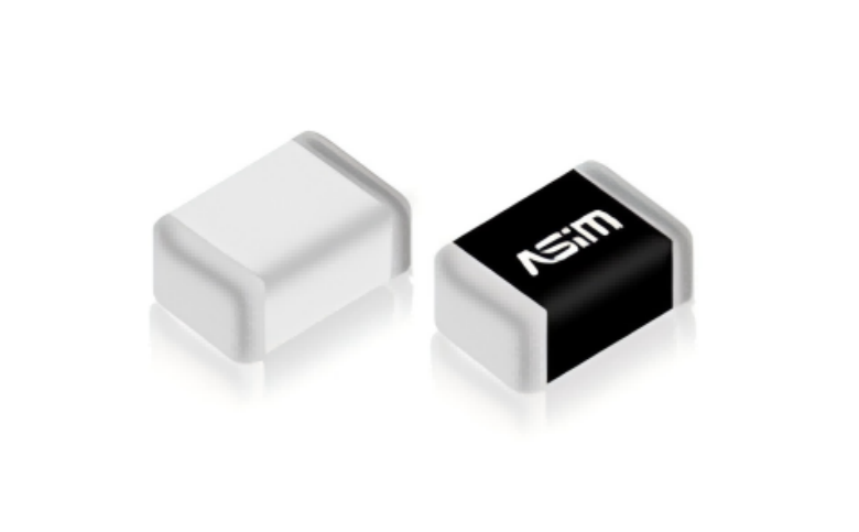
ASIM ESD3V3X004SA and ESD5X004SA are bidirectional four-channel arrays in DFN2010-5L packages. Both list 0.25 pF typical junction capacitance, while their reverse working voltages are 3.3 V and 5 V. ESD3V3X004SA has a 4.2 V minimum breakdown voltage; ESD5X004SA has a 6 V minimum breakdown voltage. Both list 6 A peak current and 12 V maximum clamp voltage at the stated conditions.
This information supports a voltage-window and channel-allocation review. It does not prove unrestricted interchangeability. The engineer still has to measure the line voltage, examine the receiver limit, confirm bidirectional topology, inspect the shared return path, and test the target PCB. Purchasing should confirm that the approved document revision and reel label remain tied to the qualified model.
Named product data is more useful than a general statement that a manufacturer offers many ESD diodes. It allows the customer to ask a precise question and creates a traceable link among brand, part number, electrical condition, and application.
Qualify lot consistency with incoming rules
Lot consistency should be managed through measurable incoming checks, not a verbal guarantee. Depending on the application's risk, the plan may cover reverse leakage, breakdown range, dimensions, marking, solderability, and sample retention. When a critical parameter is published only as typical, the buyer and manufacturer should agree on a practical acceptance method before mass production.
Record the lot code and board position for any failure. ESD-device damage does not always become a hard short. Increased leakage, shifted breakdown behavior, or an open protection path can affect the product while a simple continuity test still looks normal.
The manufacturer's response to a failure should distinguish component anomaly from electrical overstress, PCB overshoot, incorrect polarity, or a return-path problem. That analysis requires the customer to provide the stress waveform, discharge location, operating state, board revision, and surrounding circuit. Sending a burned part without system information rarely produces a useful conclusion.
Evaluate technical support by the questions it can answer
Useful support can explain parameter conditions, help narrow suitable voltage and topology classes, review a proposed land pattern, and interpret an abnormal sample result. It should also identify when the application requires board-level measurement rather than claim that a catalog rating guarantees compliance.
Ask the supplier to respond to a concrete design scenario. For example: a 3.3 V four-line interface has one pin back-driven during power-off, the connector-to-array route is 18 mm, and the receiver limit is tight. A technically useful answer will request missing conditions and discuss voltage window, leakage, return path, and validation. A purely sales-driven answer will repeat the catalog rating.
Questions for an ESD supplier approval meeting
Can an online ESD diode manufacturer ranking replace qualification?
No. Public rankings rarely evaluate the exact part number, measurement conditions, production lot, interface behavior, or failure support. Use rankings only for discovery, then complete document, sample, and incoming-quality reviews.
Is a stated IEC 61000-4-2 level enough to approve the part?
No. A component-level rating does not become the finished product's immunity level. Clamp behavior, discharge point, PCB path, enclosure, operating mode, and performance criterion remain part of the system result.
What should be checked first in a domestic replacement?
Compare topology, pinout, VRWM, VBR, VC with its current and waveform, capacitance, leakage, package, and land pattern. Then repeat signal and system-level ESD tests on the same board revision.
The final approval should name the exact model, permitted interface, PCB revision, document revision, sample lots, and test result. That record is more useful than a general statement that the supplier is qualified.
 Previous