





 Submit


Electromagnetic Compatibility Testing Project
 2025.02.24 00:00:00
 730
730





Test purpose
Check whether the voltage fluctuations caused by electronic and electrical equipment to the public power grid meet the limit requirements stipulated by relevant international and domestic standards.
Corresponding standards
IEC 61000-3-3, GB 17625.2
Measurement range
Equipment with each phase input current ≤ 16A
Concept: Test for voltage fluctuations and flickering, mainly measuring the changes in grid voltage caused by the EUT. The interference generated by the voltage variation is not only dependent on the amplitude of the voltage variation, but also on its frequency of occurrence. Voltage variations are usually evaluated using two types of indicators, namely voltage fluctuation and flicker. The voltage fluctuation indicator reflects the degree of sudden and significant voltage changes, while the flicker indicator reflects the continuous voltage changes over a period of time. In the voltage fluctuation and flicker circuit, the composition of the reference impedance Z of the power supply source S (at 50Hz).
Harmonic current testing
Testing objective
To verify whether the harmonic current injected by electronic and electrical equipment into the public power grid complies with the limit requirements stipulated in relevant international and domestic standards.
Corresponding standards
IEC 61000-3-2, GB 17625.1
Measurement range
Equipment with each phase input current ≤ 16A
Harmonic current impact:
• Overheating of the neutral line in a three-phase power supply system
• Premature damage to the phase angle adjustment capacitor
• Excessive heat loss in the transformer
• Lighting equipment with dimmers may be affected by harmonics
• Harmonics coupled into communication cables can cause noise
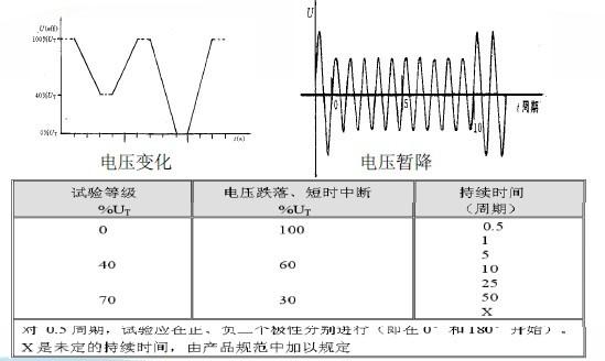
Voltage sag immunity test
Test purpose
To verify whether the performance degradation of electronic and electrical equipment during voltage sag and short-term interruption complies with the requirements of relevant international and domestic standards.
Corresponding standards
IEC 61000-4-11, GB 17626.1
Measurement range
0~100% UT
Standard definition scope:
• Electrical and electronic equipment is affected by voltage sags, short-term interruptions, or voltage fluctuations in the power supply.
• Voltage sags and short-term interruptions are caused by faults in the power grid, power facilities, or sudden large changes in load. In some cases, there may be two or more consecutive sags and interruptions. Voltage changes are caused by continuous variations in the load connected to the power grid.
• These phenomena are essentially random, and their characteristics can be expressed in terms of the deviation from the rated voltage and the duration.
Surge Immunity Test
Test Objective
To verify whether the performance of electronic and electrical equipment meets the requirements stipulated by international and domestic standards when subjected to switches or lightning strikes.
Corresponding standards
IEC 61000-4-5, GB 17626.5
Measurement range
-4.1kV to +4.1kV
The lightning surge mainly simulates indirect lightning strikes (equipment usually cannot withstand direct lightning strikes), such as:
1. The lightning strike hits the external (outdoor) lines, with a large amount of current flowing into the external lines or the grounding resistance, resulting in interference voltage.
2. The induced voltage or current on the external lines or internal lines due to an indirect lightning strike (such as between clouds or within a cloud).
3. The electromagnetic field established around the object adjacent to the line, causing the external lines to induce voltage.
4. The nearby ground struck by lightning, with the ground current introduced through the common grounding system causing interference.
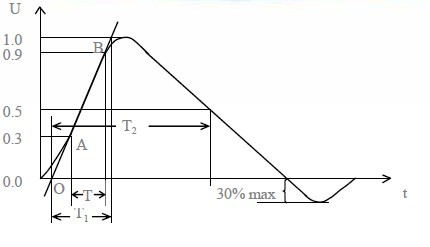
Surge generator waveform
Surge voltage wave: This waveform diagram shows a voltage wave with a leading edge and a half-peak of 1.2us/50us.
Leading edge time: T1 = 1.67T = 1.2μs ± 30%
Half-peak time: T2 = 50μs ± 20%
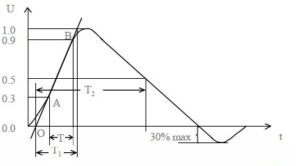
Surge current waveform: This waveform diagram represents a current wave with a leading edge and a half-peak of 8us/20us.
Leading edge time: T1 = 1.25T = 8μs ± 20%
Half-peak time: T2 = 20μs ± 20%
Electrical Fast Transient Pulse Cluster Immunity Test
Test Objective
To determine whether the performance of the power supply ports, signal and control ports of electronic and electrical equipment meets the requirements stipulated by relevant international and domestic standards when subjected to electrical fast transient pulse clusters.
Corresponding standards
IEC 61000-4-4, GB 17626.4
Measurement range
-4.4kV to +4.4kV
Meaning:
The power grid consists of primary and secondary circuits. Most of the measurement and control equipment operates on the secondary circuit. Due to the electrical and magnetic connection between the primary and secondary circuits, interference signals can be transmitted through transformers, transformers, and spatial coupling. These interference signals, after analysis, are rapid pulses, also known as fast transient electrical pulse groups. Their characteristics include short rise time, high repetition rate, and low energy. Such fast transient electrical pulse groups can now be simulated and generated using instruments.
Standard source:
In order to evaluate the anti-interference performance of electronic equipment against interference from relays, contactors, etc. when switching inductive loads on power lines, control lines and signal lines. This standard is formulated by quantifying such interference which has the characteristics of short rise time, high repetition frequency and low energy.
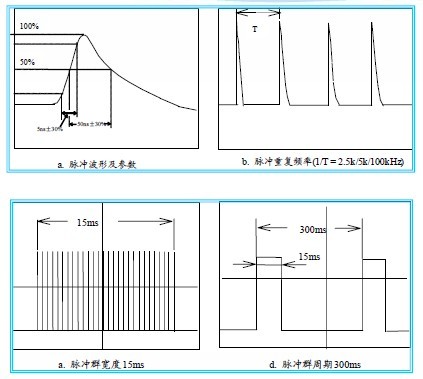
Pulse group waveform parameters:
• Pulse repetition frequency: Related to the selected test level
• Rise time of a single pulse: 5 (1 ± 30%) ns
• Pulse duration (50% value): 50 (1 ± 30%) ns
• Pulse group duration: 15 (1 ± 20%) ms
• Pulse group period: 300 (1 ± 20%) ms
• Polarity: Positive polarity, negative polarity
Pulse group waveform
Electrostatic discharge immunity test
Test purpose
To determine whether the performance of electronic and electrical equipment meets the requirements stipulated by international and domestic relevant standards under the electrostatic discharge test environment.
Corresponding standards
IEC 61000-4-2, GB 17626.2
Measurement range
-30kV to +30kV
When a charged object approaches or touches a conductor, the charges will transfer, which is the phenomenon of static discharge.
Static discharge is a ubiquitous natural phenomenon that affects electronic products everywhere and is a highly hazardous electromagnetic energy. Only by improving the anti-static capability level of electronic products can the safe use of automotive electronics be guaranteed. The automotive electronic static immunity test is carried out in accordance with ISO10605 GB/T19951-2005. Generally speaking, the static discharge test refers to the standard IEC61000-4-2. The static discharge experiment mainly simulates the direct contact of a charged human body with the tested item and the resulting discharge.
There are two types of electrostatic discharge tests: one is direct discharge, which includes contact discharge and air (gap) discharge. The other is indirect discharge, which includes horizontal coupling discharge and vertical coupling discharge.
Conductive immunity test
Test purpose
To detect whether the performance of electronic and electrical equipment meets the requirements stipulated by international and domestic corresponding standards when exposed to radio frequency emission electromagnetic interference within the frequency range of 9kHz to 80MHz.
Corresponding standards
IEC 61000-4-6, GB 17626.6
Measurement range
150kHz - 80MHz
Test site
Shielding room
Under normal circumstances, the size of the equipment that is being interfered with is much smaller than the wavelength of the interfering frequency. However, the length of the equipment's leads (including power lines, communication lines, and interface cables, etc.) may be comparable to several wavelengths of the interfering frequency. Thus, these leads can cause interference to the equipment through conduction. The test is conducted to evaluate the conductance immunity of electrical and electronic equipment to the conductance caused by the induction of radio frequency fields. For equipment without conductive cables (such as power lines, signal lines, or ground lines), this test is not required. Automotive electronic equipment, like other ordinary electronic equipment, also needs to undergo conductance immunity testing.
Radiation Immunity Test
Test Objective
To verify whether the performance of electronic and electrical equipment meets the requirements stipulated by international and domestic relevant standards when exposed to electromagnetic radiation.
Corresponding standards
IEC 61000-4-3, GB 17626.3
Measurement range
30 MHz to 3.3 GHz
Test site
9M * 6M * 6M (LWH) radio wave anechoic chamber
The radio frequency radiation electromagnetic field immunity test (standard IEC 61000-4-3 and GB/T 17626.3) establishes a common basis for evaluating the ability of electrical and electronic equipment to resist radio frequency radiation electromagnetic field interference.
Radiation interference test
Test purpose
To detect whether the interference field strength of the electronic and electrical equipment through space radiation meets the limit requirements stipulated by relevant international and domestic standards.
Corresponding standards
CISPR 22, GB 9254, FCC
Measurement range
26 MHz to 3 GHz
Test site
9M * 6M * 6M (LWH) radio wave anechoic chamber
Radiation interference mainly refers to the phenomenon where energy is emitted by a source in the form of electromagnetic waves into space or energy propagates in the form of electromagnetic waves in space. Radiation interference is an important aspect of electromagnetic compatibility and is also the project that is the most difficult to pass and the hardest to rectify during testing. When discussing the failure of electromagnetic compatibility testing, the first thing that comes to mind is the excessive radiation interference (Re F); products with excessive radiation interference may cause the performance of surrounding devices, equipment or systems to deteriorate or cause damage to living or non-living substances. It is necessary to rectify and meet the requirements of relevant regulations and standards, and only then can the product successfully enter the market.
Interrupted Interference Test
Test Objective
To verify whether the intermittent interference voltages and currents conducted by electronic and electrical equipment through power lines, interconnections, and signal lines comply with the limit requirements stipulated in relevant international and domestic standards.
Corresponding standards
CISPR14-1, GB 4343.1
Measurement range
150kHz - 30MHz (150kHz, 500kHz, 1.4MHz, 30MHz)
Test site
8M * 3M * 3M (LWH) shielded room
Intermittent disturbance testing is also known as chirping sound testing. This requirement exists in the electromagnetic compatibility testing of household appliances. Intermittent disturbance is caused by the instantaneous action of mechanical electronic switches.
Compared with continuous disturbance, the interference caused by intermittent disturbance at the audio and video output terminals of radios and televisions is different in people's subjective perception because it appears in the form of short pulses. For this reason, the limit for intermittent disturbance can be appropriately relaxed. The extent of relaxation is related to the amplitude, width and frequency of the pulses. When the frequency is expressed as the chirping rate N (N is the number of chirps within one minute), the limit for chirping sound can be increased by 44dB (N < 0.2) or 20lg(30 / 30) at the continuous disturbance limit. The situation indicates that when the number of chirps within one minute is greater than 30 times, the limit for chirping disturbance will be the same as that for continuous disturbance; conversely, when the number of chirps is no more than 5 times, its limit can be relaxed by 44dB (relaxed to more than 100 times).
Chirping sound disturbance should be tested at four points within the specified frequency range of 160kHz, 500kHz, 1.4MHz and 30MHz. The detailed regulations are not described here. They can be referred to in relevant standards.
Interference power test
Test purpose
To verify whether the electromagnetic interference power emitted by electronic and electrical equipment through power lines, interconnections, and signal lines complies with the limit requirements stipulated in relevant international and domestic standards.
Corresponding standards
CISPR14-1, GB 4343.1
Measurement range
30 MHz - 300 MHz
Test site
8M * 3M * 3M (LWH) shielded room
Interference power, also known as electromagnetic compatibility, refers to the ability of a device or system to operate within its electromagnetic environment in accordance with requirements without generating intolerable electromagnetic interference to any devices in the environment. Therefore, interference power includes two aspects of requirements: on the one hand, it means that the electromagnetic interference generated by the device during normal operation to the surrounding environment should not exceed a certain limit; on the other hand, it means that the device has a certain degree of anti-interference capability, that is, electromagnetic sensitivity, to the electromagnetic interference existing in the surrounding environment.
Tri-band antenna test
Test purpose
To verify whether the energy emitted by the lighting equipment through space radiation complies with the limit requirements stipulated in the relevant international and domestic standards.
Corresponding standards
CISPR 15, GB 17743
Measurement range
9kHz - 30MHz
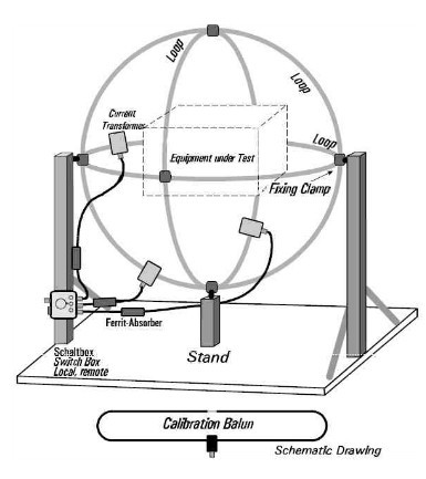
(1) Introduction to the three-loop antenna testing system
In order to meet the requirements of the lamp standards for testing the low-frequency magnetic field disturbances generated within the frequency range of 9kHz to 30MHz, a circular antenna system as specified in the CISPR 16-1-4 standard needs to be adopted.
(2) Layout of the three-loop antenna testing
The three-loop antenna consists of three mutually perpendicular large loop antennas (generally with a diameter of 2 meters). By switching through a coaxial switch, one of the three loops is connected to the EMI receiver for measurement. Generally, the measurement should be conducted in a shielded room (it is recommended that the size of the shielded room be no less than: length 5 meters, width 4 meters, height 3.5 meters), which provides good repeatability and comparability.
Insertion loss test
Test purpose
To verify whether the insertion loss of the lighting equipment complies with the limit requirements stipulated in the relevant international and domestic standards.
Corresponding standards
CISPR 15, GB 17743
Measurement range
150kHz - 1605kHz
Test site
8M 3M*3M (LWH) shielded room
Principle of insertion loss test
Power noise is a type of electromagnetic interference. The spectrum of its conducted noise is approximately 100Hz - 300MHz, with the maximum reaching 150MHz. Depending on the direction of propagation, power noise can be divided into two major categories: one is external interference introduced from the power inlet line; the other is noise generated by electronic equipment and conducted through the power line. This indicates that noise is a two-way interference signal. Electronic equipment is both the target of noise interference and a noise source. If viewed from the formation characteristics, noise interference is divided into two types: differential mode interference and common mode interference. Differential mode interference is the noise between two power lines (referred to as line-to-line); common mode interference is the noise between two power lines and the ground (referred to as line-to-ground). Therefore, electromagnetic interference filters should meet the requirements of electromagnetic compatibility (EMC) and must be bidirectional RF filters. On the one hand, they should filter out external electromagnetic interference introduced from the AC power line; on the other hand, they should also avoid the equipment itself emitting noise interference to the outside, so as not to affect the normal operation of other electronic devices in the same electromagnetic environment. In addition, electromagnetic interference filters should also suppress both differential mode and common mode interference.
 Previous

Related News

2024.12.22
The three laws of EMC (Electromagnetic Compatibility) rectification
2024.11.28
Which is the better EMC testing service provider in Shenzhen? What are the main projects of EMC testing?
2025.02.21
Several methods for rectifying electromagnetic compatibility issues
2025.02.21
Product Electromagnetic Compatibility Test - Electromagnetic Compatibility Rectification Suggestions
2026.08.06
How to Choose Between Unidirectional and Bidirectional TVS Diodes
2026.08.08
Common TVS Diode Failure Modes: Short, Leakage, and Open Circuit


