





 Submit


The influence of signals on radiation
 2025.02.24 00:00:00
 480
480





The influence of signals on radiation
The signal ground is the path by which the signal current returns, rather than the surface of the equipotential conductor. Although engineers hope that the signal follows the designed path back to the signal source, there is no guarantee that this will always happen! In fact, some spectral components of a signal will return to the signal source along one path, while other spectral components of the same signal may return along another path. A shielded cable on the grounding plane is a good example. Spectral components below the cutoff frequency of the shielded grounding circuit will return along the grounding plane, while those above the cutoff frequency will return along the shielding layer, not along the grounding plane. Therefore, it is necessary to remember that electronic circuits do not read circuit diagrams. We often focus on the path by which the signal transmits from the source to the load and rarely consider or completely ignore the path by which the signal returns to the source. To effectively carry out EMC design, it is necessary to determine and carefully design the return path of the signal.
Considering the signal in this way leads to two outcomes:
(1) The entire path has a loop area.
(2) The signal returns to the conductor. A large loop area increases the radiation emission generated by the current passing through this loop, so large loops must be avoided.
As shown in the following figure:
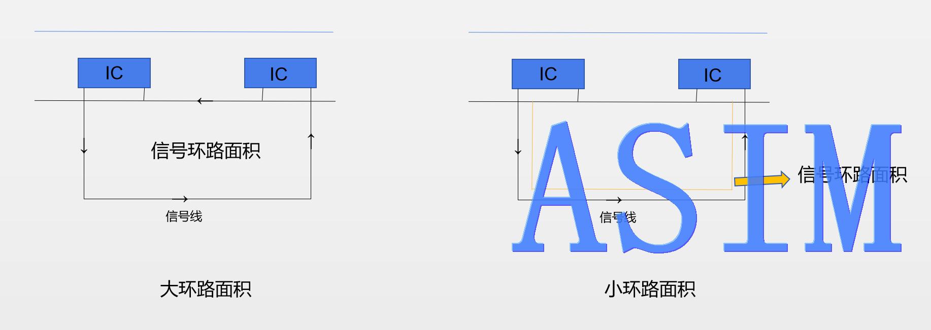
The engineer on the PCS only provides a single long path for the signal return. This results in a large loop area, which increases the radiation and reflection of the signal. If an alternative path is provided near the "signal output" path, then the loop area will significantly decrease and the radiation emission will also be significantly reduced.
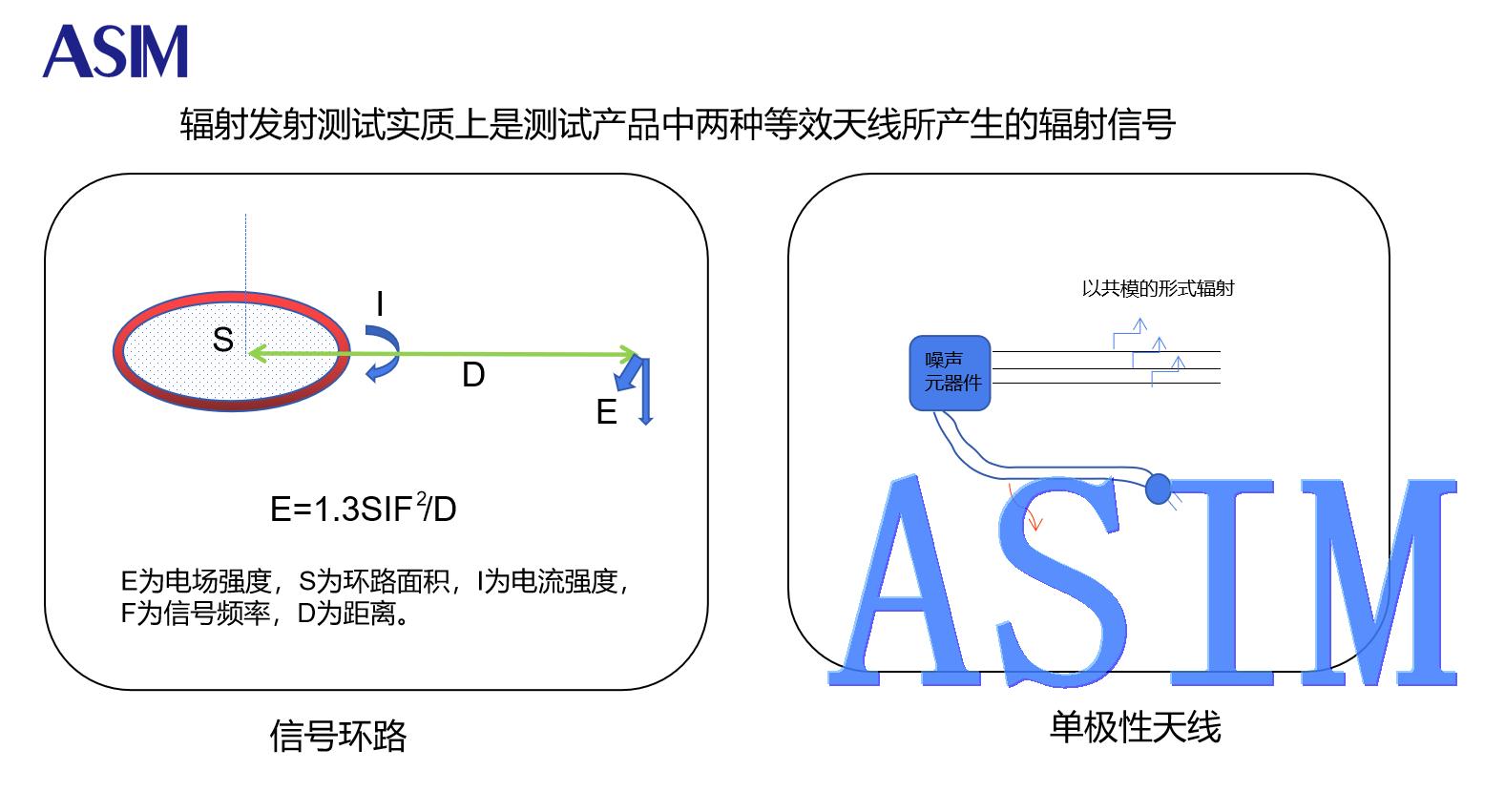
The second consequence of viewing the signal as the path by which the power returns to the signal source is the resistance of the circuit path and the high-frequency current flowing through them. Therefore, the conductor is no longer an equipotential surface. This promotes interference coupling in the form of common impedance coupling between subsystems. The impedances of these circuits and the signal output paths are all related to the loop impedance, and at high frequencies, they mainly exhibit inductive characteristics.
 Previous

Related News

2024.12.18
Test standards for automotive electronic load rejection shock tests
2025.02.21
Several methods for rectifying electromagnetic compatibility issues

2025.02.21
How to choose the best circuit protection devices in a circuit?

2026.08.05
How to Read IEC 61000-4-2 Ratings for ESD Diodes: Component Rating vs System Compliance
2026.08.07
How to Estimate TVS Diode Dynamic Resistance From VC and IPP
2026.09.05
How to Identify an ESD Diode When the Package Marking Is Incomplete


