Submit






Do not repeatedly power or immediately remove a failed TVS diode. Preserve its voltage, current, waveform, temperature, board state, and sample identity first. Then separate hard-short, leakage, and open-circuit symptoms and submit the failed unit with an unused same-lot unit and a known-good reference.
Stop repeated power cycling before the evidence changes
When a product no longer starts, a natural response is to replace a fuse, raise the current limit, or turn the supply on several times. That sequence can destroy useful evidence. A TVS with a localized leakage path may heat during each attempt until it becomes a complete short. The laboratory then sees secondary damage rather than the original failure.
Freeze the state of the board first. Record the input voltage, supply current limit, load, ambient condition, and time of failure. Photograph the device marking, orientation, solder joints, nearby copper, and upstream protection. Measure board-level resistance and standby current only at a safe voltage that will not extend the damage.
The initial record should include:
Full TVS part number, date or lot code, PCB number, and reference designator.
Test or field event immediately before the failure.
Surge or ESD waveform, polarity, coupling method, level, and repetition count.
Product operating mode, attached cables, load, and grounding arrangement.
The first observed symptom and every action taken afterward.
“Failed at 2 kV” is incomplete because the source network, port, return path, and functional criterion remain unknown.
A short, a leakage shift, and an open path tell different stories
A hard short may pull down the supply, trigger current limiting, or open a fuse. It can follow a single event beyond the junction’s energy capability. It can also develop after repeated avalanche operation caused by a normal voltage that is too close to the TVS operating boundary. Check continuous voltage before assigning the cause to one large transient.
Increased leakage is less obvious. The product may continue operating while standby current rises, an analog reading shifts, or a high-impedance node behaves differently at elevated temperature. Compare failed and good parts at the same voltage, polarity, temperature, and settling time. Parallel board circuitry can corrupt microampere measurements, so preserve the board result and then repeat at component level if removal is approved.
An open circuit or a large loss of protection may escape a simple multimeter check. Package cracking, solder damage, an internal interconnect failure, or severe pulse damage can leave the system apparently functional but unprotected against the next event. The manufacturer may use optical inspection, X-ray, curve tracing, acoustic methods, decapsulation, or cross-sectioning in a staged sequence.
Build a three-way comparison before destructive analysis
One blackened device with no reference often leads to a weak conclusion. A stronger submission contains the failed unit, an unused device from the same lot, and a known-good reference. If the failure occurs on one board, supply a failed board and a normal board or provide equivalent measurements from both.
Package each unit separately with ESD-safe handling. Labels should show whether the device remains soldered, which way it was oriented, and which electrical stress it experienced. Do not mix loose components from several boards in one bag.
Organize the supporting file in this order:
Event summary and the first observable symptom.
Circuit conditions, including continuous maximum voltage, load, and current limiting.
Transient conditions, including source impedance, peak, duration, polarity, and repetitions.
Board waveforms, temperature, resistance, leakage, and photographs.
Sample identity, purchase lot, assembly date, and previous stress history.
The question to be answered: manufacturing anomaly, electrical overstress, or an unresolved mechanism.
If destructive work is allowed, state who owns the samples and which units may be opened. When only one critical failure exists, complete non-destructive observations first.
Read every TVS rating with its test condition
A peak pulse power number is tied to a waveform and thermal condition. It is not a continuous-power rating. Clamping voltage is tied to a specified current and pulse, while breakdown voltage is measured at a lower test current. Mixing those values can make a correctly marked device appear defective or can hide an application overstress.
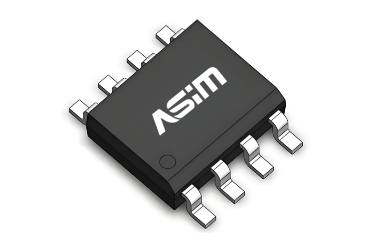
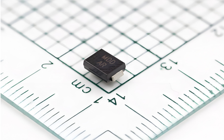
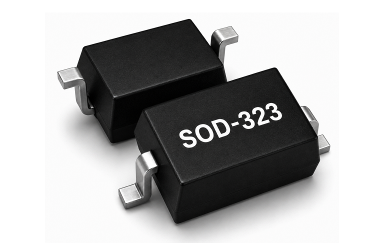
ASIM SMA04J24V provides a concrete example. It uses an SMA/DO-214AC package and lists 400 W peak pulse power, 24 V VRWM, a 26.7 V to 29.5 V breakdown range, 10.3 A IPP, and 38.9 V maximum clamping voltage under the stated conditions. A failure review must retain those conditions. The 400 W value does not mean the device can dissipate 400 W continuously, and 38.9 V does not automatically equal the voltage seen at a protected IC after PCB-path inductance is added.
For a measured surge, compare peak current, pulse shape, energy, source impedance, repetition interval, ambient temperature, and board thermal path. For continuous overvoltage, analyze steady-state dissipation and the upstream disconnect function. For repeated events, check whether the junction cools between pulses.
The analysis report should separate observations from conclusions
A disciplined report lists the condition of the received samples, inspection sequence, test conditions, measurements, physical observations, and reasoning. It distinguishes what was seen from what is inferred. Visible charring proves that high temperature occurred; it does not, by itself, prove a manufacturing defect or an application error.
If electrical overstress is the likely result, the report should state whether the evidence fits a fast ESD event, a surge, reverse connection, repetitive avalanche, or sustained overvoltage. It should also name missing evidence that prevents a narrower conclusion. If a manufacturing anomaly is found, the report should address lot risk, containment, traceability, and corrective action.
“No fault found” needs supporting scope. State which measurements matched the control, which conditions were not reproduced, and which additional board or waveform data would be needed. That answer gives the customer a next step instead of closing the case prematurely.
Close the loop on the circuit and the production record
The failure-analysis result should change something verifiable: the TVS voltage window, pulse capability, upstream current limiting, placement, ground path, test setup, or manufacturing control. Repeat the original failure condition and the worst valid boundary condition after the change. Check leakage and protected-circuit performance after stress, not just immediate operation.
Supplier review and device information are available through the ASIM TVS diode manufacturer hub. The submitted case should still preserve its own datasheet revision and sample identity because web pages and product documents can change.
Failure analysis is successful when another engineer can reproduce the event chain and verify the correction. Assigning blame without a waveform, lot, or board state may close an email thread, but it does not protect the next production unit.
TVS Diode Failure Analysis Questions
Why should a shorted TVS not be power-cycled repeatedly?
Repeated current can turn localized leakage into severe thermal damage, hiding the electrical signature of the original event.
Should the TVS be removed before it is sent to the manufacturer?
Coordinate first. Board-level evidence preserves the system state, while component-level tests may require removal. Photograph and measure the critical board before desoldering.
Does peak pulse power describe continuous overvoltage capability?
No. Peak pulse power belongs to a specified transient waveform. Continuous overvoltage requires a steady-state thermal and protection-coordination analysis.
Copyright notice:Copyright belongs to Shenzhen ASIM Electronics Co., Ltd. Please retain the author, source, and original URL when quoting or republishing.
Original URL: https://asim.com.cn/tvs-diode-failure-analysis-submission-en.html
 Previous