





 Submit


How to Rectify EMC Conducted Emission Failures? Troubleshooting Methods Ranging from Frequency Point Identification to Power Supply Filtering
 2026.07.28 00:00:00
 88
88





If EMC conducted emissions exceed limits, do not rush to add ferrite beads or double the capacitance of filter capacitors. Instead, first standardize the test setup and identify the relationship between the frequencies where limits are exceeded and the switching frequency, clock, or load status; then, determine whether the noise is returning to the LISN via differential mode or common mode. Misidentifying the mode leads to increasingly complex filter designs without necessarily lowering the emission levels.
When performing actual troubleshooting, I typically start by establishing a baseline curve for reference and then modify only one variable at a time. The ASIM CVB1608V121T is a candidate ferrite bead for local power supply branches: it features a 1608 package, an impedance of 120 Ω ±25% at 100 MHz, a maximum DCR of 0.45 Ω, and a maximum rated current of 600 mA. Its effectiveness depends on the frequency range where the limit is exceeded, the DC bias, and the mounting location; one cannot draw a conclusion based solely on the "120 Ω" specification.
First, finalize the test setup.
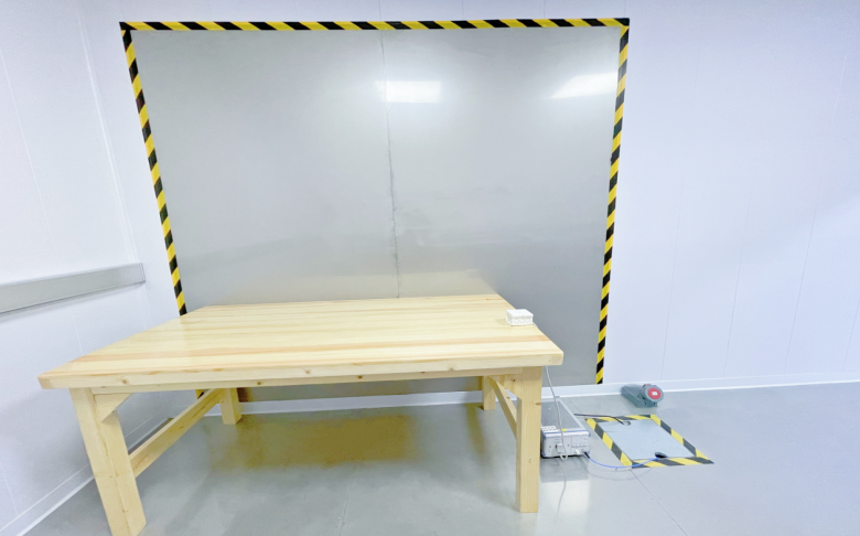
Conducted emission curves are highly sensitive to cable length, the ground plane, LISN placement, load status, and the power supply method. Before implementing corrective measures, restore the setup to the configuration specified by the target standard and record the receiver bandwidth, detection mode, scan range, and limit lines. If the settings used for pre-scanning differ from those used for certification testing, the resulting curves cannot be directly compared.
The device's operating state must also be kept constant. Factors such as wireless module transmission, motor operation, display brightness, and DC-DC converter loading can all alter the spectrum. When comparing results before and after remediation, the firmware version, input voltage, and load must remain identical; otherwise, a variation of a few decibels might stem from the operating conditions rather than the components themselves.
It is recommended to save the raw scan data rather than just a single screenshot. The raw data is more useful for subsequent analysis—such as examining the difference between peak and quasi-peak values, observing an overall rise in a specific frequency range, or verifying whether a narrowband peak has shifted.
Back-calculate the noise source from frequency points exceeding limits.
If peaks appear near the fundamental switching frequency or its integer multiples, first check the input capacitor current, the switching loop, and the frequency jitter settings. Regular harmonics in the lower frequency range are often associated with differential-mode input current; conversely, if a broadband hump or a cluster of closely spaced spikes appears at higher frequencies, attention should be paid to switching node ringing, diode reverse recovery, and parasitic coupling.
When a frequency component aligns with the edges of digital clock, PWM, crystal oscillator, or communication signals, the power line may merely serve as a path for noise to exit the product, while the actual source lies within the digital circuitry. In such cases, simply upgrading the power line filter might suppress part of the emission curve without addressing the root cause.
A practical approach is to make small adjustments to the switching frequency or clock frequency and observe whether the peak exceeding the limit moves in sync. If the peak shifts accordingly, the scope of the source can be narrowed down. This test is intended solely for localization purposes; the final settings must still comply with product functionality and regulatory requirements.
Failing to distinguish between common mode and differential mode can easily lead to misguided rectification efforts.
Differential-mode currents flow in opposite directions through the positive and negative power lines and primarily originate from the pulsating current drawn during normal device operation. Common mitigation measures include minimizing the high-frequency current loop, adding input capacitance near the switching components, and designing an appropriate differential-mode LC or Pi-type filter at the power input.
Common-mode current flows in the same direction along both the positive and negative lines and returns via the chassis, reference ground, or parasitic capacitance. It is often generated through coupling at nodes with high dv/dt; factors such as parasitic capacitance to ground, heat sinks, shielding, and cable placement can all influence the outcome. Addressing common-mode issues requires a focus on common-mode inductance, high-frequency return paths to the chassis, and the surface area of the noise source.
Assessment can be aided by calculations using a common-mode/differential-mode separation network or a dual-channel LISN, or by clamping a current probe around the entire power cable bundle. When both the positive and negative lines are passed through the probe simultaneously, ideal differential-mode currents cancel each other out, leaving high-frequency components that more closely represent the common-mode current. Baseline calibration of the probe and clamping method should be performed beforehand.
If differential-mode noise exceeds limits, first check the input current loop.
The input bypass capacitor of a switching power supply should be placed close to the high-di/dt loop; the traces connecting the capacitor to the switching device and the power ground should not take a circuitous route. The presence of a large capacitor at the input does not mean the high-frequency current loop near the chip is effectively closed; if the traces are too long, parasitic inductance will allow pulsed current to continue flowing into the power supply lines.
Once the layout is finalized, design the differential-mode filter based on the target frequency band. While a series inductor or ferrite bead combined with a shunt capacitor forms a low-pass network, the filter design cannot rely solely on the calculated cutoff frequency. The interaction between the power supply input impedance and the filter output impedance can lead to resonance—causing a rise in the response curve over certain frequency ranges—and may also degrade power supply transient performance due to insufficient damping.
A capacitor's effective capacitance varies with DC bias, temperature, and package type. Although a component may be specified as 10 μF on the schematic, its actual capacitance under operating voltage conditions may be significantly lower. Once the modified prototype passes validation, the specific part number, bias conditions, and tolerance must be documented in the review records.
If common-mode emissions exceed limits, the return path must be supplemented.
A common-mode inductor presents impedance to high-frequency currents flowing in the same direction on both lines, while having a relatively minor impact on normal differential-mode currents. It is suitable for placement at boundaries where noise might cross, such as near power connectors. If there is a large area of copper foil downstream of the component that forms parasitic coupling with the chassis or external cables, common-mode current may bypass the filter.
A capacitor connected to the chassis can provide a short return path for high-frequency common-mode currents, provided that safety standards, leakage current limits, and the grounding structure allow for it. For products lacking a chassis ground, arbitrarily adding "Y-capacitors" might simply shift noise from one location to another; the actual return path must be mapped out first.
Adjusting the area of the switching node, slowing down excessively fast edges, and optimizing transformer winding or heatsink coupling are often more effective than simply adding more common-mode inductors at the input. Reducing displacement currents at the source lightens the load on the filter.
Ferrite bead parameters must correspond to the frequency range where limits are exceeded and to the current requirements.
The 120 Ω rating specified for the CVB1608V121T applies to the 100 MHz test point; it does not imply that the impedance remains constant across the range from several hundred kilohertz to several hundred megahertz. Before using the component for conducted emission remediation, one should examine the full impedance curve to determine the real and imaginary parts of the impedance within the frequency bands where limits are exceeded, and verify how the impedance changes under DC bias conditions.
The maximum rated current of 600 mA is not the recommended operating point. Design margins must be allowed for actual branch current, startup peak current, and ambient temperature; furthermore, the maximum DCR of 0.45 Ω will result in voltage drop and heat generation. If the power supply branch operates at currents exceeding 1 A, this component cannot be used directly, even if its frequency characteristics are suitable.
Ferrite beads are better suited for blocking the outward propagation of localized high-frequency noise. If the issue is low-frequency differential-mode ripple, a filter network composed of inductors and capacitors is usually more direct; if the problem involves common-mode current across a cable bundle, then common-mode chokes and chassis return paths should be evaluated. The choice of component type should be dictated by the noise mode.
If components are misplaced, even the highest specifications are wasted.
The filter should be placed between the noise source and the external cables, effectively separating the "dirty zone" and the "clean zone" on the PCB. If the copper planes on either side of the ferrite bead overlap significantly across adjacent layers, high-frequency current can couple across via parasitic capacitance. Additionally, a high-speed trace running alongside the filter could re-couple noise to the connector side.
The circuit loop for a shunt capacitor must be kept short. If a capacitor is connected to a distant ground plane and the return path to the noise source involves a long, thin trace, the actual high-frequency impedance may be significantly higher than expected. When using the chassis as a reference for common-mode filtering, the connection point should be close to the interface to prevent high-frequency currents from flowing through the system's digital ground.
Temporary "flying leads" used to modify a board can help determine the direction of a fix, but the leads themselves introduce inductance and alter the circuit loop. The final production board must be re-tested based on the actual layout; results obtained from external components attached to a prototype cannot simply be treated as design margin.
Only one key variable is changed during each re-test.
Remediation is often inefficient because multiple changes—such as swapping inductors, adding capacitors, adjusting frequencies, or applying copper foil—are made simultaneously; consequently, even if the curve improves, it is impossible to determine which specific modification was effective. If any of these steps are omitted in the next board revision, the problem recurs.
A more reliable approach is to first establish a baseline and then sequentially verify the source, the transmission path, and the receiver. For each test, retain the differential curve and document the components, locations, and test conditions. Once a modification is confirmed effective, evaluate temperature rise, startup behavior, load transients, and overall functionality to ensure that achieving EMC compliance does not compromise power supply stability.
The criterion for concluding corrective actions is not merely bringing levels below the limit line; allowances must also be made for manufacturing tolerances, cable variations, operating modes, and test laboratory repeatability. The magnitude of these margins should be determined based on product risk and corporate standards rather than by applying a fixed numerical value.
Common Issues in Conducted Emission Rectification
Is it acceptable to start by increasing capacitance to address excessive conducted emissions?
It can serve as a diagnostic step, but the design should not be finalized based on this alone. Capacitors are more effective against differential-mode noise but can also trigger input filter resonance, startup inrush current issues, or changes in loop stability. One should first identify the noise mode before determining the appropriate capacitance and damping.
Does higher ferrite bead impedance always yield better results for conducted emission mitigation?
No. Factors such as the impedance curve within the problematic frequency range, DC bias, DCR, and rated current must be considered. Excessively high impedance can create new resonances with capacitors or cause a voltage drop in the power supply.
Can common-mode inductors solve all conducted emission issues?
No. They specifically address common-mode current. If the primary issue is differential-mode input ripple, the focus should be on high di/dt loops, input capacitance, and differential-mode filtering.
Can the product be submitted for certification immediately after passing a pre-scan?
No; the setup must be restored to the official configuration—including cables, ground planes, loads, and receiver settings—and checked against peak, quasi-peak, or average limit requirements. Pre-scans serve to narrow down issues, but the final verdict relies on formal testing against the target standard.
Remediation for conducted emissions boils down to a single engineering logic: first identify the frequency points exceeding limits, then determine the mode in which the current returns to the LISN, and only then select components and placement. Without the first two steps, filter implementation is often just a matter of trial and error.
 Previous

Related News
2026.07.15
For what applications are SOD-323 packaged ESD diodes suitable?
2026.07.17
How should the design be rectified if the power port fails the surge test?
2026.07.20
How should a failure in the CAN communication surge test be handled?
2026.07.20
How do you design a TVS protection solution for automotive power supplies?
2026.07.23
How do you implement ESD protection for USB Type-C interfaces? You need to select separate solutions for the data lines, CC lines, and VBUS.
2026.07.23
How to Design ESD Protection for HDMI Interfaces? Key Selection Criteria for TMDS High-Speed Lines and Control Lines

2026.07.24
What are the differences between SMA, SMB, and SMC packaged TVS diodes? Selection based on power and size.
2026.07.24
How to Select a TVS Diode for the Power Input: A Complete Process from Operating Voltage to Clamping Voltage
2026.07.24
How to Choose Between Unidirectional and Bidirectional TVS: A Comparison of DC Power Supplies, AC Signals, and Communication Interfaces
2026.07.25
Why Must Pulse Waveforms Be Considered When Selecting TVS Diodes for Automotive Electronics? Key Points for ISO 7637 Applications


