





 Submit


How to Choose Between Unidirectional and Bidirectional TVS: A Comparison of DC Power Supplies, AC Signals, and Communication Interfaces
 2026.07.24 00:00:00
 78
78





When choosing between unidirectional and bidirectional TVS diodes, first consider whether the normal voltage of the circuit—relative to the reference ground—crosses 0 V. Unidirectional TVS diodes are generally preferred for DC power supplies that remain consistently positive; conversely, for AC lines or bipolar signals that exhibit both positive and negative swings during normal operation, a bidirectional TVS diode capable of covering the operating range in both directions should be selected.
Both types of devices can handle transients of either positive or negative polarity, but their conduction modes differ when a negative voltage occurs. Incorrect polarity selection may result in signal clipping; furthermore, if the power supply is connected in reverse, the TVS could enter a state of continuous conduction and sustain damage.
The current paths for unidirectional and bidirectional flow are different.
A typical unidirectional TVS clamps voltage via avalanche breakdown in one direction, while conducting in the forward direction like an ordinary diode in the opposite direction. Consequently, its clamping voltage for negative pulses is typically lower; however, the device cannot withstand significant negative voltage for extended periods during normal circuit operation.
Bidirectional TVS devices exhibit approximately symmetrical breakdown regions in both positive and negative directions. As long as normal peak voltages do not exceed the reverse working voltage (VRWM) in either direction, the device remains in a high-impedance state, making it suitable for AC and bipolar circuits. The trade-off is that negative-polarity events are not clamped at the level of a single diode's forward voltage drop; consequently, downstream circuitry must be capable of withstanding the resulting negative residual voltage.
The model designation indicates only part of the series conventions. Different manufacturers use different suffixes—such as 'A' for unidirectional and 'CA' for bidirectional, or 'B', 'C', and others—so these cannot be applied across brands. Verifying the internal structure, I-V curve, polarity markings, and pin definitions is more reliable than relying on the suffix.
Observe polarity differences using the ASIM 24V model.
Taking the SMA04J24V and SMA04J24B as examples, the former is a unidirectional TVS, while the latter is a bidirectional TVS. Both have a VRWM of 24 V and a VBR range of 26.7–29.5 V; at the specified IPP of 10.3 A, both exhibit a maximum VC of 38.9 V.
The fact that the forward avalanche parameters in the table are similar does not mean the components are interchangeable. The SMA04J24V conducts in the reverse direction just like a standard diode, making it better suited for DC power supplies where the voltage remains positive and reverse-fault current limiting is already implemented. The SMA04J24B retains a breakdown window in both positive and negative directions, making it more suitable for circuits where the normal waveform crosses 0 V.
The "V" and "B" here denote the polarity for this specific group of ASIM models. When switching to other series or brands, the suffix conventions may differ; therefore, you should always refer back to the configuration, internal structure, and I-V curves to verify.
Why are unidirectional TVS diodes commonly used in DC power supplies?
When a unidirectional TVS is used with a positive DC power supply referenced to ground, the cathode is typically connected to the positive terminal and the anode to ground. A positive surge drives the device into the avalanche region, whereas a negative surge or reverse connection may cause it to conduct in the forward direction, thereby clamping the negative voltage to a lower level.
This does not mean that a unidirectional TVS can replace reverse-polarity protection. If the power supply is connected in reverse and the upstream source continues to deliver power, the TVS will create a high-current path. This clamping method is only effective if a fuse, current-limiting switch, or electronic protection circuit can cut off the energy in time; otherwise, both the TVS and the PCB traces could overheat.
Bidirectional TVS diodes can also be used in DC power supplies subject only to positive surges; however, unlike unidirectional devices, they do not immediately conduct in the forward direction upon reverse connection. If the downstream circuitry cannot tolerate negative voltage, separate reverse-polarity protection is required. When choosing between the two, one must separately evaluate the risks of positive surges and reverse-polarity connections.
For AC lines, VRWM should be selected based on the peak voltage.
AC lines undergo periodic voltage swings between positive and negative polarities, making bidirectional TVS diodes the more common choice. When selecting the reverse standoff voltage (VRWM), one must consider the maximum peak voltage—accounting for input tolerances, no-load voltage rise, and waveform distortion—rather than simply comparing the RMS value to the VRWM.
For applications such as low-voltage AC lines, motor sensors, or audio circuits, actual peak voltages and overshoots can differ even if nominal RMS values are identical. The TVS operating window (spanning both positive and negative polarities) must encompass the normal waveform, while the clamping voltage (VC) must remain below the transient withstand limit of the downstream circuitry.
If two unidirectional TVS diodes are connected in anti-series to create a bidirectional clamping solution, factors such as device matching, PCB footprint, and parasitic effects from interconnections must be evaluated. While this configuration is useful for certain high-energy applications or specific voltage combinations, it should not be assumed to be automatically equivalent to a standard bidirectional TVS diode.
Communication interfaces cannot be evaluated solely based on differential voltage.
When selecting components for differential interfaces such as CAN or RS-485, one must consider the voltage range of each individual line relative to ground. A small differential amplitude between the two lines does not guarantee that a single line will not experience negative voltage; factors such as common-mode range, ground potential difference, bus faults, and power-down states must all be taken into account.
If the signal swings across 0 V during normal operation, a standard unidirectional TVS might conduct prematurely during the negative half-cycle. Bidirectional devices better preserve the bipolar operating window, though parameters such as VRWM, VC, and negative residual voltage must still align with the ratings of the transceiver's bus pins.
For high-speed or high-frequency interfaces, junction capacitance and package parasitic effects must also be considered. Power TVS diodes (such as SMA, SMB, or SMC types) intended for power supply inputs often have capacitance levels unsuitable for direct connection to high-speed data lines. Instead, low-capacitance arrays designed for the specific interface should be selected, with polarity determined based on the line-to-ground voltage rather than the interface name.
Similarly, VRWMs cannot be directly interchanged.
While forward avalanche parameters for unidirectional and bidirectional TVS devices of the same voltage rating may be similar, their negative-polarity I-V curves differ significantly. When selecting a replacement, one must compare not only the VRWM (Working Peak Reverse Voltage) but also the VBR (Breakdown Voltage) range, VC (Clamping Voltage) at the target IPP (Peak Pulse Current), leakage current, junction capacitance, and temperature derating.
Package markings must also be checked. Unidirectional devices typically feature polarity markings, whereas bidirectional devices may not require specific orientation—though this is not a universal rule. Internal array configurations may include a common ground, a common power rail, or multiple back-to-back channels; installing the device backward or misconnecting the common terminal will alter the discharge path.
When selecting a TVS device, one should first define the circuit's Vmin, Vmax, and reference ground, and then verify the surge waveform and the voltage withstand rating of the downstream components. Simply specifying a "bidirectional TVS" without defining the operating voltage window makes it impossible to determine whether the voltage rating is appropriate.
Surge verification must cover both polarities.
When using a unidirectional TVS at the power input, both positive and negative pulses must be verified. For positive surges, the focus is on avalanche clamping and temperature rise; for negative pulses, the evaluation covers forward current, upstream current limiting, and the downstream circuit's ability to withstand reverse voltage.
For bidirectional lines, pulses of both polarities should be applied separately to verify the positive and negative clamping voltages (Vc), waveform recovery, and communication status. Symmetrical parameters in the device datasheet cannot substitute for system-level test results; factors such as ground loops and PCB traces between the connector and the protection device can increase residual voltage during fast-transient pulses.
Common Questions About Unidirectional and Bidirectional TVS Diodes
Can a unidirectional TVS protect against negative surges?
Yes. A standard unidirectional TVS will conduct in the forward direction when subjected to a negative pulse. Whether it can safely withstand the surge depends on the pulse current, duration, the device's forward current capability, and the PCB circuit path.
Can a bidirectional TVS be used with a DC power supply?
Yes, provided the downstream circuitry can tolerate negative voltage. A bidirectional TVS does not necessarily conduct under typical reverse-polarity conditions, so it cannot simply serve as a substitute for reverse-polarity protection.
Can a bidirectional TVS be replaced by two unidirectional TVS devices?
While some circuits can utilize two unidirectional TVS devices connected in anti-series, parameters such as total clamping voltage, junction capacitance, power distribution, and package parasitics will change. Re-calculation and verification based on the complete I-V characteristics are required; one cannot simply swap a single device for two based solely on voltage ratings.
Should bidirectional TVS devices always be selected for communication interfaces?
No. The choice depends on factors such as the normal signal voltage range relative to ground, common-mode voltage, data rate, and the transceiver's voltage tolerance. Some unipolar interfaces are suited for unidirectional, low-capacitance devices, whereas certain bus systems require specialized bidirectional or asymmetrical protection arrays.
Before finalizing the design, clearly define the minimum and maximum operating voltages (Vmin/Vmax), normal peak voltages, surge polarities, target peak pulse current (IPP), downstream voltage tolerance (positive and negative), and junction capacitance limits. Only by evaluating these conditions can you determine whether a unidirectional or bidirectional TVS is appropriate.
 Previous

Related News
2026.06.22
ESD Diode vs TVS Diode: Which to Use and When
2026.07.13
How do I select a 5V low-capacitance ESD diode model?
2026.07.15
For what applications are SOD-323 packaged ESD diodes suitable?
2026.07.16
How do I select the package for a TVS diode used with a 24V power supply?
2026.07.17
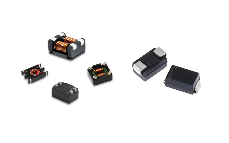
How should TVS diodes and common-mode inductors be configured for a CAN interface?
2026.07.17
How do you choose between SMA, SMB, and SMC packaged TVS diodes?
2026.07.20
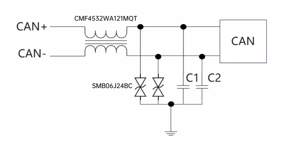
How should a failure in the CAN communication surge test be handled?
2026.07.20
For which automotive applications is the SM8S series TVS suitable?
2026.07.23
How to Design ESD Protection for HDMI Interfaces? Key Selection Criteria for TMDS High-Speed Lines and Control Lines

2026.07.24
What are the differences between SMA, SMB, and SMC packaged TVS diodes? Selection based on power and size.


