





 Submit


How should TVS diodes and common-mode inductors be configured for a CAN interface?
 2026.07.17 00:00:00
 118
118





In CAN interfaces, TVS devices are primarily used to suppress ESD and surge-induced transient overvoltages, while common-mode chokes serve to suppress common-mode noise and improve EMI performance. Although these components perform different functions and are often used in combination, their layout sequence, component parameters, and impact on signal integrity must be determined based on factors such as the CAN data rate (e.g., 500 kbps for Classic CAN or several Mbps for CAN FD), the cabling environment (e.g., ISO 7637-2 scenarios like automotive load dump or reverse battery connection), and the required test levels (e.g., IEC 61000-4-2 for ESD and ISO 7637-2 for electrical transients).
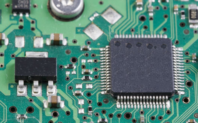
I. What problems do TVS diodes and common-mode inductors address?
A TVS (Transient Voltage Suppressor) features a response time in the picosecond (ps) range and is used to clamp overvoltages on the CANH and CANL lines to safe levels. For instance, automotive CAN bus designs often employ bidirectional TVS diodes connected from the CAN+/CAN- lines to ground (such as the SMBJ24CA or the equivalent ESD24B300TBC from Asymtek—a 24V-class bidirectional device) to ensure compliance with ISO 7637-2 pulse testing and IEC 61000-4-2 ESD standards. Common-mode inductors are used to suppress common-mode interference, helping to mitigate both radiated emissions and conducted disturbances. A typical automotive-grade common-mode filter, such as the CMF4532WA121MQT, offers a common-mode impedance of 120Ω ±25% at 100MHz, an extremely low DC resistance (DCR) of 0.07Ω, and a rated current of 3A; it is also commonly recommended to connect a 100pF capacitor to ground in parallel to filter out high-frequency noise.
Since CAN interfaces are susceptible to electrostatic discharge (ESD), surge events, and potential EMI limit violations, TVS diodes and common-mode inductors are frequently used together in protection solutions.
II. Typical Layout Strategies
A common approach is to place protection components near the interface entry point: TVS diodes are used to rapidly discharge transient energy (positioned at the CANH/CANL lines relative to ground), while common-mode chokes are placed in the signal path to suppress common-mode noise. The specific sequence should be determined based on test requirements and board-level layout; however, standard automotive CAN design practices dictate that common-mode chokes be placed in series with the differential lines and TVS diodes be positioned close to the interface. Additionally, strict length matching for CAN+/CAN- lines is required (length difference < 5 mm), with trace width and spacing calculated to achieve a 120Ω differential impedance. Parallel routing alongside high-frequency signals (such as PWM or CLK) must be avoided, maintaining a spacing of at least three times the trace width.
The distances between the termination resistor, common-mode choke, TVS, and transceiver affect waveform quality, immunity, and EMI performance; the return path for transient currents should be short and continuous.
III. Selection Considerations
For TVS diodes, key parameters include working voltage (VRWM must exceed the bus's normal operating voltage; e.g., a 24V-rated component for a 24V system), clamping voltage (VC must be lower than the transceiver's withstand voltage), peak pulse current (IPP), and capacitance (low capacitance minimizes signal leakage). For common-mode chokes, focus on the impedance curve (typically 120Ω at 100 MHz), rated current, DC resistance (low DCR, such as 0.07Ω, reduces signal loss), and the impact on signal integrity at the specific CAN data rate.
CAN FD operates at higher data rates and is more sensitive to the parasitic parameters of common-mode chokes and TVS diodes; excessive capacitance or unsuitable impedance can compromise communication. Therefore, it is advisable to select automotive-grade common-mode filters with excellent high-frequency characteristics (such as the CMF3225WA series) and low-capacitance TVS diodes (such as the ESD36R120TA, designed specifically for automotive low- and high-speed CAN networks).
IV. ASIM Solutions
ASIM offers TVS and ESD devices for CAN interfaces, common-mode chokes (such as CMF4532WA121MQT and CMF2SMFWI110M), and EMC rectification recommendations. Backed by a professional EMC laboratory, these solutions are suitable for automotive central control units, cameras, T-BOX systems, industrial CAN applications, and communication control equipment, with comprehensive technical support and customization available—ranging from component selection to PCB layout.
FAQs
Q: Is it sufficient to use only a TVS diode for the CAN interface?
A: It can meet some ESD/surge protection requirements; however, addressing EMI issues (such as excessive radiated or conducted emissions) may still require the addition of a common-mode choke.
Q: Can a common-mode choke replace a TVS diode?
A: No. Common-mode chokes suppress noise, while TVS diodes suppress transient overvoltage; they serve different functions and are not interchangeable.
Q: What should be considered for CAN FD interfaces?
A: Attention must be paid to component capacitance, impedance, and speed compatibility to avoid distorting communication waveforms; priority should be given to components with low parasitic parameters that are suitable for high-speed differential signals.
 Previous

Related News
2025.09.05
ESD5E001TA Bidirectional TVS Diode Technical Specification -ASIM

2026.06.12
TVS Diode Selection Guide for 800V Electric Vehicle Systems: High-Voltage Platform Protection
2026.06.22
TVS Diode VRWM, VBR, and VC: Parameter Relationship Guide
2026.07.08
Are SM8S series TVS diodes suitable for automotive power supplies?
2026.07.11
How is the ESD0524 series used for USB interfaces?
2026.07.13
How should ESD protection devices be laid out for a Type-C port?
2026.07.13
What should be done if a USB interface fails ESD testing?
2026.07.15
For what applications are SOD-323 packaged ESD diodes suitable?
2026.07.16
Common Issues Regarding ESD Protection for HDMI Interfaces
2026.07.16
How do you design a surge protection solution for industrial power supplies?


