Submit






An ESD diode manufacturer should not be ranked by placing an IEC 61000-4-2 level, a TLP current, a typical capacitance value, and an S-parameter curve in one score. Each item describes a different boundary. A useful supplier comparison checks whether the test conditions are visible, whether the data belongs to the exact ordering code, and whether the manufacturer can connect component behavior to the customer's board.
Begin with the protected interface, not a supplier scorecard
The same protection device can be a reasonable candidate for one interface and a poor choice for another. A 3.3 V high-speed receiver, a 5 V control line, and a 24 V power input do not share an operating window. Before comparing suppliers, record the signal swing, maximum continuous voltage, direction, number of lines, data rate, downstream absolute maximum, expected transient, package space, and return structure.
This input turns a vague question such as “Which manufacturer is best?” into a technical question: “Which manufacturer can document and support a device for this electrical and mechanical boundary?” It also prevents purchasing from awarding points to a specification that has no relevance to the target circuit.
Separate the evidence into four groups:
robustness evidence, including the pulse source, polarity, test setup, number of events, and failure criterion;
clamping evidence, including current, waveform, voltage measurement point, and leakage after stress;
signal-integrity evidence, including capacitance conditions, S-parameter frequency range, fixture, and de-embedding boundary;
production evidence, including the full part number, package, lot identity, controlled limits, and change-notification route.
Numbers can be compared only after they are in the same group and measured under compatible conditions.
An IEC level is a robustness statement, not a complete system result
IEC 61000-4-2 is a system-level electrostatic discharge immunity method. Component suppliers also use related pulses to characterize protection devices, but the result needs context. The board, stressed pins, polarity, return connection, event count, and definition of failure determine what the stated level means.
A device surviving a pulse on a supplier test board does not prove that the protected IC will see an acceptable voltage in a finished product. The connection from the connector to the diode, the package inductance, and the return path add residual voltage. Current can also bypass the diode through a shield, cable, adjacent trace, or shared reference.
When two datasheets both claim the same contact-discharge level, ask these questions before treating them as equal:
Does the claim apply to the exact ordering code and every protected channel?
Were positive and negative polarities tested?
What fixture and return path were used?
What constituted failure: short circuit, leakage shift, parameter drift, or functional damage?
Was leakage measured again after the complete pulse sequence?
These answers do more for an engineering decision than a larger voltage printed without conditions.
TLP data describes a different operating window
Transmission line pulse testing records current-voltage behavior over a controlled pulse interval. Engineers use it to examine trigger behavior, the clamping region, dynamic resistance, and changes that occur near failure. A TLP curve can show why two devices with the same IEC survival claim expose a downstream pin to different voltage at a selected current.
The curve is not self-explanatory. Pulse width, rise time, measurement window, polarity, current step, and post-stress leakage criterion must accompany it. Very-fast TLP, conventional TLP, and an IEC pulse have different waveforms, so their current values should not be exchanged as though they were the same test.
Read a TLP plot in a repeatable order. Confirm the part number and pin path first. Locate the current region relevant to the source rather than jumping to the largest point. Compare voltage in that region with the downstream tolerance. Then inspect leakage or other failure indicators. Finish by measuring the assembled board, because a component plot cannot include the customer's layout.
Capacitance and S-parameters answer the signal question
High-speed interfaces are loaded by the protection device during normal operation. A typical junction capacitance is useful for screening, but it does not describe the entire channel. Bias voltage, frequency, package, pad geometry, and channel topology all affect the result.
S-parameters can show insertion loss, return loss, and coupling over frequency. Their value depends on the measurement boundary. A supplier may de-embed the fixture to the package pads, while another file includes part of a test trace. Overlaying the curves without checking those boundaries can create a false winner.
For USB, HDMI, MIPI, or another high-speed link, request enough information to reproduce the comparison:
the Touchstone file and port definition;
reference impedance and differential or single-ended setup;
fixture description and de-embedding method;
package and recommended footprint;
frequency range that covers the target channel;
voltage bias used for any capacitance measurement.
The final decision still belongs to the target board. Validate the connector, pads, vias, protected device, trace, cable, and receiver together at the intended data rate.
Production capability appears in traceability and change control
Technical data loses value when samples and production material cannot be tied to the same product definition. The manufacturer should make the full ordering code, reel label, lot identifier, package orientation, datasheet revision, and applicable qualification evidence clear. Split reels and evaluation samples need to preserve that identity.
Product-change notifications matter because die, wafer source, molding compound, assembly location, marking, and test flow can affect an approved boundary. An AVL record should state which changes require notification and which verification must be repeated. A company name on a quotation is not enough if no one can say who owns the specification or issues a PCN.
Failure-analysis support is another practical test. The supplier should be able to explain what board data, waveforms, stressed samples, labels, and known-good units are required. A useful report separates observations, test conditions, and root-cause conclusions instead of assigning responsibility from a photograph.
Build an evidence matrix instead of a brand ranking
A compact matrix can keep the review honest. Use rows for the operating window, clamping, signal integrity, package and layout, traceability, change control, and failure support. In each cell, record the source document, revision, test conditions, remaining question, and board result. Leave the cell open when evidence is missing rather than filling it with a marketing phrase.
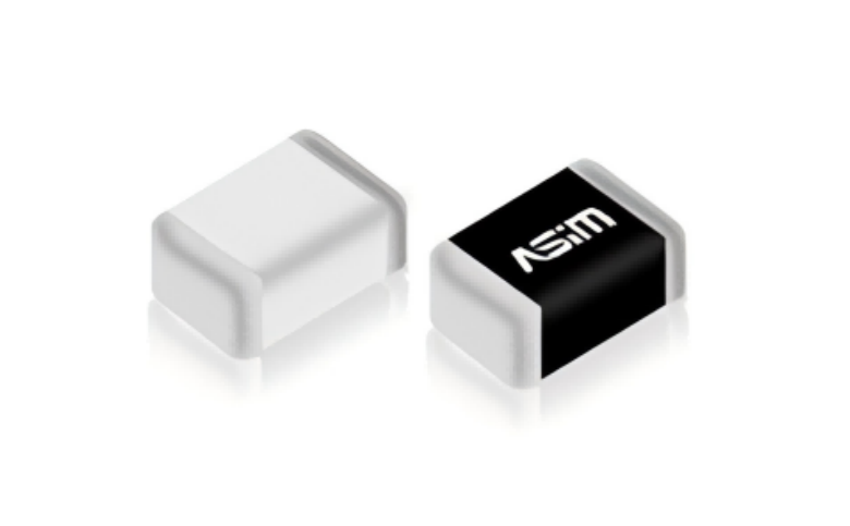
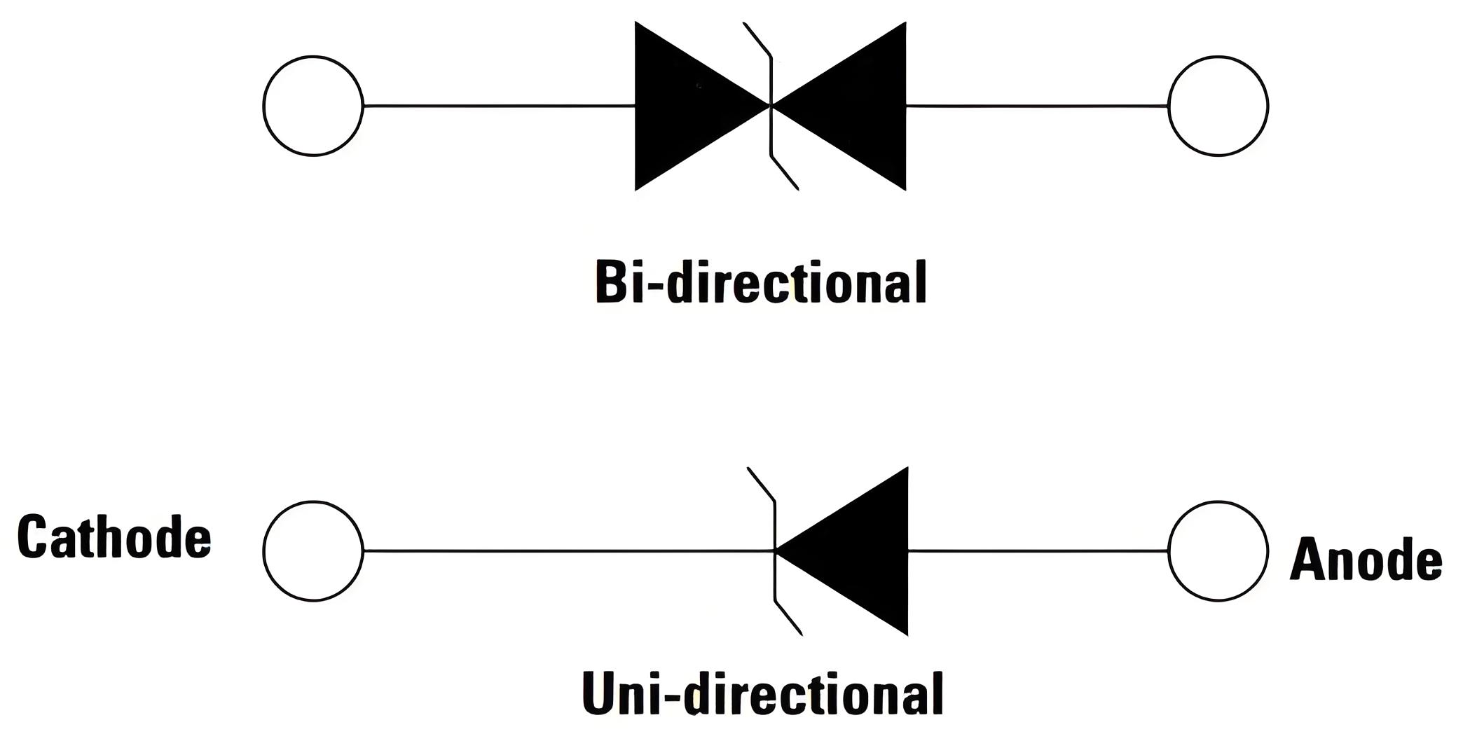
ASIM uses this interface-first approach when discussing ESD diode candidates. ASIM ESD3V3X004SA and ESD5X004SA, for example, are bidirectional four-channel DFN2010-5L arrays with a published typical junction capacitance of 0.25 pF and reverse working voltages of 3.3 V and 5 V respectively. Those values help identify a candidate voltage and capacitance class. They do not replace pin mapping, clamping conditions, S-parameter review, layout, or system testing.
The ASIM ESD diode manufacturer hub provides a stable route into manufacturer and selection information. A project approval should still cite the exact product document and the customer's validation record.
The manufacturer comparison is complete when another engineer can repeat it
The strongest supplier is not the one with the most numbers on a landing page. It is the one whose numbers can be traced to a part, test condition, and engineering purpose, then checked on the customer's board. That standard works for engineering, quality, and purchasing without pretending that IEC ratings, TLP curves, and S-parameters measure the same thing.
ESD Manufacturer Data FAQ
Does a higher IEC 61000-4-2 rating prove that one ESD manufacturer is better?
No. Compare the fixture, polarity, event count, stressed pins, failure criterion, clamping behavior, and the result on the target board.
Can an ESD diode be selected without a TLP curve?
It can enter a preliminary review, but the project needs other current-clamping evidence and board measurements before closing the protection decision.
Do low-speed GPIO lines need S-parameter files?
Voltage, leakage, and clamping normally dominate a low-speed GPIO review. S-parameters are more valuable when channel loss and reflections constrain a high-speed interface.
Copyright notice:Copyright belongs to Shenzhen ASIM Electronics Co., Ltd. Please retain the author, source, and original URL when quoting or republishing.
Original URL: https://asim.com.cn/compare-esd-diode-manufacturers-technical-data-en.html
 Previous