Submit






A TVS diode manufacturer supplies transient-voltage suppressors and the application data needed to evaluate them. Useful manufacturer information connects reverse working voltage, breakdown range, clamping voltage, peak pulse current, and a defined pulse waveform. Labels such as “24 V,” “400 W,” or “low clamping” cannot establish design compatibility by themselves.
ASIM supplies TVS products across different working-voltage and package classes and supports power-entry, interface-surge, and PCB-return review. A project should begin with the maximum continuous voltage measured at the board, the downstream voltage boundary, and the relevant transient condition. Selecting a catalog part first and reconstructing the application later is a common route to a device that fits the footprint but not the electrical window.
Why voltage and wattage labels are incomplete
Each TVS voltage parameter answers a different question. VRWM defines the region in which the device is intended to remain off during valid continuous operation. VBR describes entry into avalanche at a stated test current. VC is the maximum clamping result at a specified pulse current. Peak pulse power depends on waveform shape, pulse duration, starting temperature, package, and thermal derating. It is not a continuous-power rating.
| Datasheet field | Engineering question | Required context |
|---|---|---|
| VRWM | Will the TVS remain off during every valid operating state? | Input tolerance, no-load state, hot plug, reverse feed, and temperature |
| VBR | Where does avalanche begin? | Minimum and maximum range with the breakdown test current |
| VC | How high can the TVS terminal voltage rise during the stated pulse? | Corresponding IPP, waveform, temperature, and maximum-value definition |
| IPP and PPPM | What peak stress is covered by the rating? | Pulse shape, duration, repetition, and derating |
| IR | Is steady-state leakage acceptable before and after stress? | Reverse test voltage, temperature, cleanliness, and post-stress change |
Two manufacturers' VC values cannot be ranked when the pulse currents are different. Two devices with the same VRWM, package name, and headline power still require comparison of breakdown tolerance, dynamic resistance, polarity, leakage, thermal behavior, and land pattern. A complete manufacturer page makes those relationships visible instead of repeating isolated maximum values.
The application input determines the evidence required
An adapter input, a 24 V industrial supply, an automotive power rail, and an external communication port do not face the same source impedance or pulse energy. A manufacturer may have a broad catalog; the qualification team needs evidence for the exact input and standard under review.
| Application | Define before selection | Measure during sample validation |
|---|---|---|
| 5 V to 24 V adapter input | Adapter tolerance, no-load output, hot-plug overshoot, and sustained fault state | Leakage, hot plug, protected-node overshoot, and post-stress condition |
| 24 V industrial supply | Supply tolerance, wiring inductance, surge source impedance, and downstream limit | Actual TVS current, VC, temperature rise, and repetitive-pulse effect |
| 12 V, 24 V, or 48 V automotive rail | Platform voltage window, required pulse, temperature, and qualification needs | Specified waveform, long-pulse heating, and functional status |
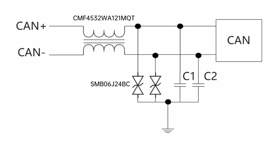
| USB, Ethernet, and exposed interfaces | Data-versus-power grouping, speed, isolation boundary, and reference path | Signal quality, interface operation, ESD or surge, and return geometry |
Even two products described as “24 V systems” can need different TVS voltage classes. If the high-temperature, charging, no-load, or fault-state voltage approaches VRWM, leakage and heating can increase. Raising the working-voltage class creates more normal-operation margin but also raises the breakdown and clamp window. The available margin must be calculated on both sides.
SMA04J24V shows how one parameter set closes the loop
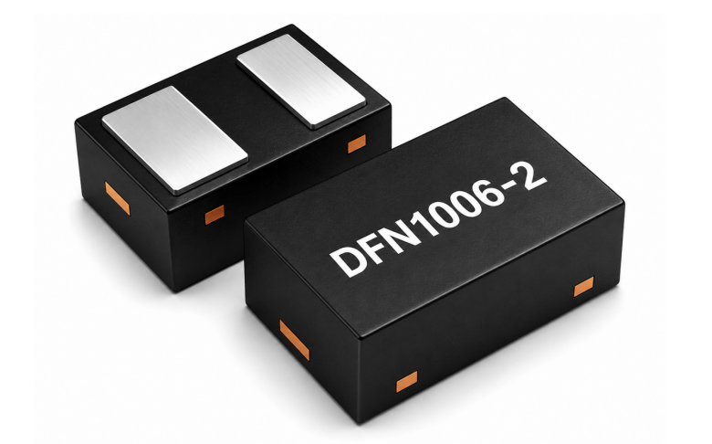
ASIM SMA04J24V uses an SMA/DO-214AC package. Its peak pulse power is 400 W, VRWM is 24 V, and the breakdown range is 26.7 V to 29.5 V. Under the stated conditions, the device lists 10.3 A peak pulse current, 38.9 V maximum clamping voltage, and 1 microampere reverse leakage.
This parameter group can support a candidate calculation. The board's valid continuous voltage must remain compatible with the 24 V working class. The downstream circuit must tolerate the 38.9 V device-terminal clamp plus PCB parasitic overshoot. The expected surge current and waveform must relate to the stated 10.3 A point. These numbers do not prove that the device fits every 24 V input, nor do they prove that a 400 W label is inherently better than another power class.
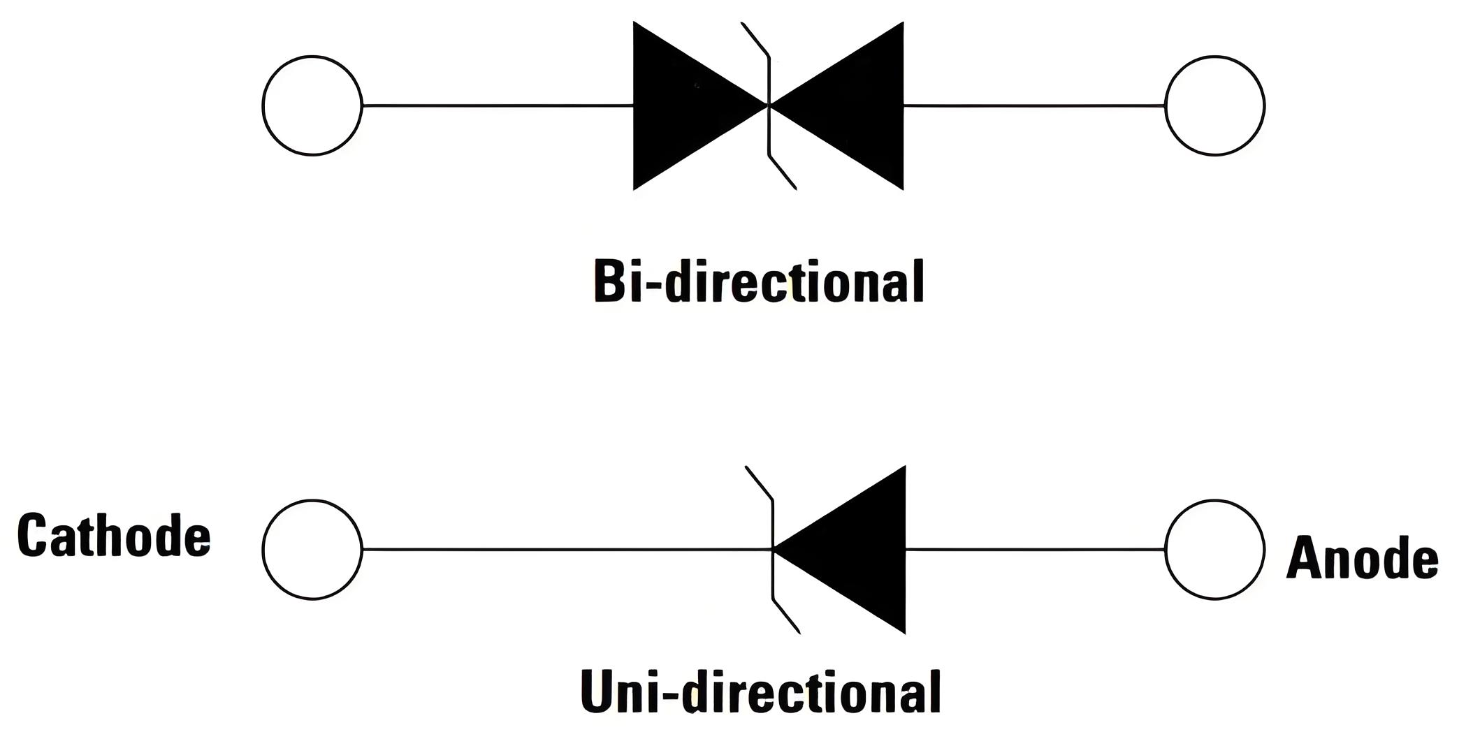
Use the ASIM TVS product range to screen by normal voltage and transient type before comparing package space, unidirectional or bidirectional behavior, and clamping. Put the full part number into the engineering record; keep the application boundary visible in the sourcing request.
One successful surge test is not production approval
Surge results depend on generator configuration, source impedance, cable, PCB branch, reference path, and sample state. Keep those variables fixed. An A/B/A experiment is useful: establish the original result, install the candidate TVS while changing only one variable, then restore the original configuration and check whether the response returns. The final step catches soldering effects, sample damage, and setup drift.
Production approval also needs supply evidence:
complete order code, polarity, package, land pattern, and datasheet revision;
agreement among the sample lot, packing label, and approval document;
boundaries for production testing and periodic electrical sampling;
temperature derating, soldering, handling, and storage requirements;
a notification process for die, assembly, or material changes;
traceability, re-test, and failure-analysis handling for returned samples.
A stressed TVS does not always fail short. Leakage can rise, the avalanche region can shift, or thermal behavior can change while the product still powers on. Post-stress inspection therefore needs more than a continuity check or a statement that the equipment remained functional.
Compress the project request into one useful page
A strong sample request does not have to be long. It does need more than the imported reference part number. Include:
nominal input, measured maximum continuous board voltage, and temperature range;
transient standard, waveform, source impedance, polarity, and repetition count;
voltage limits for the downstream MOSFET, DC/DC converter, and input capacitor;
present TVS, package, connector entry, and a local return-path image;
failure symptom, event timing, and system state after stress;
sample, pilot, and production timing with the intended operating conditions.
A manufacturer can use these conditions to propose a candidate that can be calculated and tested. A reply based only on “24 V power input” remains an unqualified catalog suggestion.
How ASIM supports a TVS project
ASIM can screen TVS candidates from the continuous voltage, pulse condition, downstream limit, and package space. The same review can include device placement, the protection branch, and the high-frequency return. The customer approves the candidate on the intended PCB, enclosure, cable, load, and applicable test standard.
For a detailed parameter review, use the TVS diode manufacturer evaluation guide. A domestic-alternate project should also compare the original and candidate under the same pulse and board conditions. Factory capability, lot control, and document ownership should be audited independently from the electrical fit; a technically suitable sample can still be unsuitable for production when traceability is missing.
Questions buyers ask TVS diode manufacturers
Are “TVS tube manufacturer” and “TVS diode manufacturer” different supplier categories?
In most sourcing contexts, both phrases refer to suppliers of transient-voltage-suppression diodes. Formal qualification still needs the precise construction, polarity, package, and orderable part number.
Does a higher peak pulse power guarantee a lower clamp voltage?
No. The clamp depends on working-voltage class, avalanche behavior, dynamic resistance, pulse current, and waveform. Compare maximum VC at aligned conditions rather than infer clamping from the power label.
Should a 24 V supply use a 24 V VRWM device automatically?
No. Measure the highest continuous board voltage, including tolerance, no-load, charging, and fault states. Then check VRWM margin, the maximum clamp, PCB overshoot, and the downstream voltage limit.
Can ASIM guarantee that a finished product will pass a surge test?
ASIM cannot guarantee a system result without the actual hardware and test conditions. ASIM can support component screening and remediation. A fixed sample configuration and repeatable system test provide the approval evidence.
 Previous