





 Submit


Why does adding a filter fail to resolve EMC issues? First, determine whether the noise is common-mode or differential-mode.
 2026.07.28 00:00:00
 91
91





If adding a filter fails to resolve an EMC issue, the common reason is that the wrong target is being addressed; the issue is not directly related to the component's nominal impedance. A differential-mode filter is placed in series within the operating current loop, while a common-mode inductor handles high-frequency currents flowing in the same direction across two lines; if noise bypasses the component via the chassis, shielding, or parasitic capacitance, even a comprehensive filtering network on the schematic will be ineffective.
The ASIM CVB1608V221T ferrite bead and CMF2012WE670MQT common-mode inductor serve as excellent examples to illustrate this distinction. The former features an impedance of 220 Ω ±25% at 100 MHz, a maximum DCR of 0.55 Ω, and a maximum rated current of 500 mA; the latter offers a common-mode impedance of 67 Ω ±25% at 100 MHz, a VDC of 50 V, a maximum DCR of 0.2 Ω, and a maximum rated current of 700 mA. These two sets of figures cannot be directly compared in terms of magnitude, as the devices differ in their connection methods and the current modes they handle.
Common-mode and differential-mode are distinguished by the direction of the current.
Differential-mode current flows into the device via the positive power line and returns via the negative line, moving in opposite directions. The device's normal operating current is inherently differential-mode current, while high-frequency components from the switching power supply's input ripple are superimposed on this path.
Common-mode current flows in the same direction along the positive and negative lines (or a pair of signal lines) and returns via the chassis, protective earth, shielding, heat sinks, or parasitic capacitance. Parasitic capacitance between high-dv/dt nodes and the reference ground is a common path for common-mode excitation.
A single device can exhibit both types of noise simultaneously, with their relative proportions varying across frequency bands. One cannot assume that high-frequency noise behaves the same way simply because the low-frequency noise is differential-mode; mitigation measures must be determined based on the specific frequency range where limits are exceeded.
When evaluating LISN results, both lines must be examined.
Conducted emission testing typically employs a Line Impedance Stabilization Network (LISN) to establish a repeatable source impedance and route noise to the receiver. If both the amplitude and phase of the two lines are captured, common-mode and differential-mode components can be calculated or derived using a separation network. While conclusions drawn from amplitude-only data are less definitive, such data can still be used in conjunction with other tests to narrow down the source of the noise.
A common supplementary technique involves clamping a high-frequency current probe around the entire bundle of positive and negative power lines. Since the magnetic fields generated by differential-mode currents ideally cancel each other out, the residual component detected by the probe closely approximates the common-mode current. By subsequently clamping the probe around individual lines and comparing their spectra and amplitudes, one can determine which mode is dominant.
Measurement fixtures are characterized by specific bandwidth, transfer impedance, and positional repeatability. Before formal assessment, zero-point and background noise checks should be performed; for comparative measurements, the clamping orientation, number of turns, and probe position must remain consistent.
Only clues can be obtained from the shape of the spectrum.
Significant low-order harmonics and switching-frequency components that vary markedly with load current often point to differential-mode input ripple. High-frequency, broadband noise that is sensitive to the positioning of cables, the chassis, and heatsinks often indicates common-mode coupling. Note that these are merely indicators; frequency alone is not the sole criterion for diagnosis.
If making minor adjustments to switching edges or reducing the switching node area results in a significant drop in high-frequency noise, common-mode excitation is likely the dominant factor. If low-frequency harmonics decrease after temporarily adding input differential-mode capacitance, the differential-mode path warrants further investigation.
You can also alter cable routing, disconnect non-essential peripherals, or temporarily improve the high-frequency connection to the chassis. If the noise profile changes in response to these actions, it indicates that the noise propagation path is linked to the external structure. Change only one variable at a time; otherwise, it becomes difficult to draw a clear conclusion.
Why does the performance of a differential-mode filter deteriorate with successive modifications?
Differential-mode LC or Pi-type filters have their own resonant frequencies; the peak response is determined by the combined effects of inductors, ferrite beads, capacitors, line impedance, and power supply input impedance. Insufficient damping can lead to amplification within specific frequency ranges, as well as oscillations during device startup or load steps.
When selecting ferrite beads, one must focus on sufficient resistive loss within the target frequency range rather than merely considering total impedance. DC bias alters the properties of magnetic materials, and capacitors can also suffer from capacitance loss under bias. Consequently, a filter designed based on small-signal, zero-bias datasheet parameters often performs differently than calculated when installed on a high-current power line.
Excessive loop length in parallel capacitor circuits can also compromise performance. High-frequency currents naturally follow the path of least impedance; even a few nanohenries of additional inductance in the capacitor's grounding path can allow noise to couple back onto the power line.
Why is there no reduction [in interference/noise] even after installing the common-mode inductor?
A common-mode inductor is designed to force the common-mode current that needs to be blocked to pass through its two windings. If a shield, chassis connection, or separate ground wire bypasses this boundary, the common-mode current can return via that alternative path; simply installing a common-mode inductor on the positive and negative power lines does not necessarily break the complete circuit loop.
If there is significant overlap between the "dirty ground" and "clean ground" areas on either side of the component, parasitic inter-layer capacitance can allow high-frequency signals to bypass the inductor. Furthermore, if the filter is placed far from the connector, the traces and copper planes connecting them may couple to the chassis or cables.
Common-mode inductors are also characterized by differential-mode leakage inductance, rated current, and DC resistance. When used in communication lines, differential-mode insertion loss and signal integrity must be verified; for power line applications, temperature rise and fault current handling must be considered. High common-mode impedance does not automatically guarantee that these other requirements are met.
Ferrite beads and common-mode inductors cannot be interchanged based solely on impedance values.
For the CVB1608V221T, the 220 Ω figure represents the impedance of the single-line ferrite bead measured at 100 MHz. It is best suited for placement in series with low-current power supply lines or signal branches to attenuate high-frequency components passing through them. Its maximum rated current of 500 mA and maximum DCR of 0.55 Ω make it unsuitable for direct placement at the main power input if the current exceeds the rated limit.
For the CMF2012WE670MQT, the 67 Ω figure represents the common-mode impedance at 100 MHz. Since the magnetic fluxes generated by the two windings largely cancel each other out regarding normal differential-mode currents, its application differs from that of a single-line ferrite bead. Its specifications—50 VDC, a maximum rated current of 700 mA, and a maximum DCR of 0.2 Ω—must still be verified against actual power supply or interface conditions.
If the emission limit violation occurs primarily around 10 MHz, the 100 MHz test point serves only as a preliminary screening metric. For final component selection, one should examine the full impedance curves, DC bias characteristics, and temperature performance of both devices, while also evaluating insertion loss within the target frequency range.
The filter position should be aligned with the region boundary.
Measures taken near the noise source aim to reduce excitation—for instance, by minimizing the switching hot loop, optimizing decoupling, and controlling edge rates. Measures taken near the connector aim to prevent high-frequency currents from entering external cables. The objectives at these two locations differ.
A common mistake is placing a ferrite bead near the connector while leaving the decoupling capacitor far away near the noise source, or installing a common-mode choke on the board while leaving a large area of copper—coupled to the chassis—on the "outer" side of the choke. These issues become immediately apparent when the high-frequency current paths are mapped out.
Traces on either side of a filter should not run parallel and close together for long distances, nor should they overlap across layers in a way that creates parasitic bypass capacitance. It is essential to clearly specify which "ground" a capacitor connects to—whether it is digital ground, the power supply negative terminal, the chassis, or protective earth; ambiguous labeling can lead remediation efforts astray.
How to verify noise patterns through ad-hoc testing?
When differential-mode noise is suspected, you can—while ensuring safety and stability—temporarily adjust the input capacitance, series impedance, or switching frequency to observe changes in low-frequency harmonics. When common-mode noise is suspected, comparisons can be made using clamp-on ferrite cores, modifying high-frequency chassis connections, or shortening cables.
These measures serve only to verify the direction of the solution. Temporary capacitors introduce lead inductance, copper foil connections involve uncontrollable contact resistance, and clamp-on ferrite cores may not be suitable for mass production. Once the noise mode is confirmed, replace these with components and PCB structures that allow for precise calculation and proper assembly.
Final re-testing must evaluate both EMC curves and product functionality. Filters can affect power supply stability, interface eye diagrams, startup times, or temperature rise; simply recording that "the curve dropped" is insufficient.
Common Questions About Common-Mode and Differential-Mode Noise
Does low frequency necessarily imply differential mode, and high frequency necessarily imply common mode?
One cannot make such an absolute judgment. While the frequency range offers clues, final confirmation requires methods such as two-wire measurements, common-mode current probes, load variation tests, and cable susceptibility analysis.
Can ferrite beads replace common-mode chokes?
Generally, they are not direct substitutes. Ferrite beads are placed in series within a single line and must withstand the operating current; common-mode chokes utilize coupled windings to target common-mode currents flowing in the same direction. The two components affect normal differential-mode signals and currents differently.
Is higher common-mode choke impedance always better?
Not necessarily. Factors such as impedance within the target frequency range, differential-mode leakage inductance, DCR, rated current, and parasitic capacitance must all be considered. If the impedance peak is far removed from the frequency point where the limit is exceeded, a high catalog impedance value offers no direct benefit.
Why does the problem recur after a PCB change, even if the filter was previously effective?
Filtering performance depends on component placement, grounding, interlayer overlap, and loop inductance. Even with an identical schematic, changes in PCB parasitic paths can alter the outcome. Effective layout configurations should be standardized and preserved, not just the Bill of Materials (BOM).
Distinguishing between common-mode and differential-mode noise is the most time-efficient step in EMC troubleshooting. Component selection—choosing between ferrite beads, common-mode chokes, and capacitors—should only be made after identifying the noise mode, target frequency range, and actual current loop.
 Previous

Related News
2026.07.17
How do you choose between SMA, SMB, and SMC packaged TVS diodes?
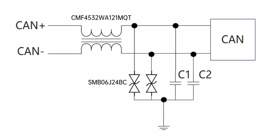
2026.07.20
How should a failure in the CAN communication surge test be handled?
2026.07.23
How do you implement ESD protection for USB Type-C interfaces? You need to select separate solutions for the data lines, CC lines, and VBUS.
2026.07.23
How to Design ESD Protection for HDMI Interfaces? Key Selection Criteria for TMDS High-Speed Lines and Control Lines
2026.07.23
How to Select Low-Capacitance ESD Protection for MIPI D-PHY Interfaces: Key Design Considerations for Camera and Display Links
2026.07.25
How to implement CAN bus protection? A combination of ESD, TVS, and common-mode choke components.
2026.07.28
How to remediate EMC radiated emission failures? Troubleshooting clocks, cables, and PCB return paths.


