





 Submit


How to Interpret TVS Diode VBR Tolerance and Temperature Shift
 2026.08.07 00:00:00
 80
80





The minimum and maximum VBR values of a TVS diode define its breakdown range at a specified test current, temperature, and measurement method. Minimum VBR helps check whether the device could enter avalanche too early during a normal overvoltage. Maximum VBR affects the starting point of worst-case surge clamping. Neither number is a substitute for VC.
Production parts can fall anywhere inside the specified VBR range. Temperature shifts the breakdown point as well. A robust design therefore cannot rely on a typical value or on a single room-temperature sample.
How are VRWM, VBR, and VC related?
VRWM is the continuous reverse working-voltage boundary where the TVS is intended to remain off. VBR is measured at a stated, relatively small test current as the device enters breakdown. VC is measured at a much larger pulse current and represents the maximum voltage at that operating point.
A useful selection record includes:
- highest continuous voltage, including tolerance, ripple, and regeneration;
- VRWM and leakage current at relevant temperature;
- minimum and maximum VBR with the associated test current;
- maximum VC at the estimated IPP and specified waveform;
- downstream transient withstand voltage and allowed duration;
- PCB and package overshoot allowance.
Using only minimum VBR can make worst-case clamping look too optimistic. Using only maximum VBR can hide the risk that a low-end sample conducts during a normal high-voltage state.
What does minimum VBR protect against?
Minimum VBR is the lowest breakdown boundary permitted by the specification. If a power rail's highest sustained voltage approaches it, low-end production parts may show increased leakage or heating when ripple, temperature, and measurement uncertainty are included.
The ASIM SMA04J24V has a VRWM of 24 V and a VBR range of 26.7 to 29.5 V. A nominal 24 V system that remains at 27 V during charging or regenerative operation cannot be assumed safe merely because the label says 24 V. The sustained overvoltage must be corrected or a different voltage class must be evaluated together with its higher clamping voltage.
Check the low-end boundary in this order:
- Measure the highest sustained voltage in every operating state.
- Include ripple, startup, shutdown, and load-release behavior.
- Compare the result with VRWM, minimum VBR, and high-temperature leakage data.
- Measure protection-branch current after the assembly reaches thermal equilibrium.
- Reject any option that depends on a typical room-temperature value.
Short spikes and sustained overvoltage must be separated. A TVS is designed for defined transients; it should not act as a continuous shunt regulator.
Why does maximum VBR affect the protection window?
Maximum VBR means that some conforming parts will reach the specified breakdown test current at a higher voltage. Pulse current then raises voltage further through the device's dynamic resistance. A downstream-voltage calculation based only on minimum VBR leaves out both tolerance and current-dependent rise.
For the SMA04J24V, maximum VBR is 29.5 V. Maximum VC is 38.9 V at an IPP of 10.3 A. The 38.9 V value is the more relevant upper boundary at that specified surge operating point. PCB inductance can add overshoot beyond it at the protected pin.
The 33 V SMA04J33V illustrates the voltage tradeoff. Its VBR range is 36.7 to 40.6 V, and its maximum VC is 53.3 V at 7.5 A. The higher voltage class reduces the chance of normal-state conduction but gives the downstream circuit a much higher residual-voltage requirement.
How does temperature shift VBR?
The temperature coefficient of avalanche breakdown depends on junction design and voltage region. One percentage should not be applied to every TVS diode. Use the coefficient or curve for the exact part when it is available. If no temperature information is supplied, do not invent a universal correction.
Temperature analysis should cover:
- whether low-temperature VBR approaches the normal voltage envelope;
- whether high-temperature behavior raises VC at the target current;
- whether leakage at high temperature affects standby power;
- whether adjacent hot components increase the starting junction temperature;
- whether repeated pulses arrive before the junction has cooled.
Hardware testing should cover room temperature and the product's relevant hot and cold limits. A room-temperature result can be reported as an interim check, but it should not be presented as full-temperature validation.
How should VBR be measured without damaging the part?
Use a source-measure unit or a controlled high-voltage supply with current limiting. Increase reverse voltage gradually and read voltage when the datasheet's VBR test current is reached. A normal multimeter diode mode rarely provides the required voltage or controlled current.
Record the following conditions:
- part number, lot, and sample count;
- VBR test current and current-limit setting;
- ambient and device starting temperature;
- voltage ramp rate and hold time;
- test polarity for a bidirectional part;
- leakage current before and after the measurement.
VBR test current is far below surge IPP. Do not use a slow DC supply to force the part into a high-power avalanche condition. Junction heating can alter the reading or damage the sample.
How should a tolerance stack be documented?
Treat normal-operation and surge boundaries as separate calculations.
For normal operation, compare the maximum sustained rail with VRWM, leakage, and minimum VBR across temperature. For surge protection, compare maximum VBR and maximum VC at the estimated current with the downstream limit. Add trace overshoot and measurement uncertainty.
The review table should identify whether each value is minimum, typical, or maximum. A frequent documentation error is to combine a typical rail voltage, typical TVS curve, and absolute maximum IC rating. That combination contains no production margin.
Common questions
Is a lower maximum VBR always better?
No. A lower breakdown point may reduce the start of clamping, but the device must still remain off at the highest continuous voltage and meet leakage and pulse-energy requirements.
Does an in-range measured VBR prove that a stressed TVS is healthy?
No. Surge damage may first appear as higher leakage while VBR remains inside the specified range. Leakage and pulse clamping should also be compared.
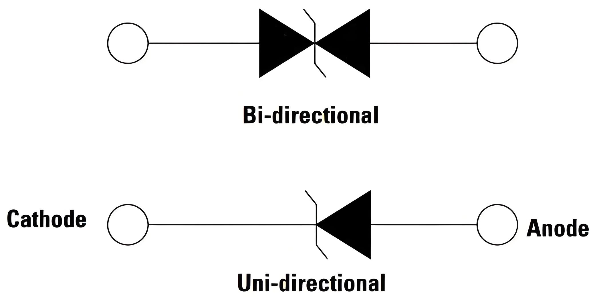
Must positive and negative VBR be identical on a bidirectional TVS?
Some difference can exist within the device specification. Both polarities should be measured when the application depends on a symmetrical AC or bipolar window.
Can VBR be used to estimate VC?
It is only one starting point. VC also depends on pulse current, dynamic resistance, waveform, temperature, and layout. VBR should not be copied into a downstream withstand calculation as the clamp voltage.
VBR tolerance serves two separate checks: the low end must stay out of normal operation, and the high end plus current-dependent voltage rise must remain within the protection window. A design is complete only when both sides have margin.
 Previous

Related News

2024.10.12
EMC testing Contents and Current Situation of Automotive Electronic products
2026.07.16
How do I select the package for a TVS diode used with a 24V power supply?
2026.07.23
How to Design ESD Protection for HDMI Interfaces? Key Selection Criteria for TMDS High-Speed Lines and Control Lines

2026.07.24
What are the differences between SMA, SMB, and SMC packaged TVS diodes? Selection based on power and size.
2026.07.25
Why Must Pulse Waveforms Be Considered When Selecting TVS Diodes for Automotive Electronics? Key Points for ISO 7637 Applications
2026.07.28
How to remediate EMC radiated emission failures? Troubleshooting clocks, cables, and PCB return paths.

2026.08.05
How to Read TVS Diode Reverse Leakage Current (IR): Temperature, VRWM, and Standby Power

2026.08.05
How to Read IEC 61000-4-2 Ratings for ESD Diodes: Component Rating vs System Compliance
2026.08.06
How to Choose Between Unidirectional and Bidirectional TVS Diodes
2026.08.07
Single-Channel ESD Diodes vs ESD Arrays: How to Choose


