Submit






A TVS replacement cannot be approved from a brand name, a voltage label, or a package code alone. The original full part number, polarity suffix, circuit operating window, pulse waveform, clamp condition, and board footprint are required before an ASIM candidate can be screened.
Direct answer: collect the original device data first, compare conditioned electrical and mechanical limits, and treat the ASIM result as a candidate. Approve the change only after sample, residual-voltage, assembly, and system surge verification on the target board.
Information required from the original TVS
A useful cross-reference request includes at least these eight inputs:
complete manufacturer part number and data-sheet revision;
unidirectional or bidirectional construction, including every suffix;
nominal and highest continuous circuit voltage;
VRWM and the minimum-to-maximum VBR range;
maximum VC together with its specified IPP;
pulse waveform, initial temperature, and peak-power rating;
package drawing, land pattern, height, and polarity mark;
protected-node limit, applicable test, source impedance, and cable condition.
If a request provides only “24 V TVS in SMA,” it does not yet define an interchangeable component.
What three 24 V ASIM examples demonstrate
The following public ASIM examples share a 24 V reverse stand-off voltage. Their pulse-current points and packages are different.
| ASIM part | Package | VRWM | VBR range | Maximum VC | Associated IPP | Power class |
|---|---|---|---|---|---|---|
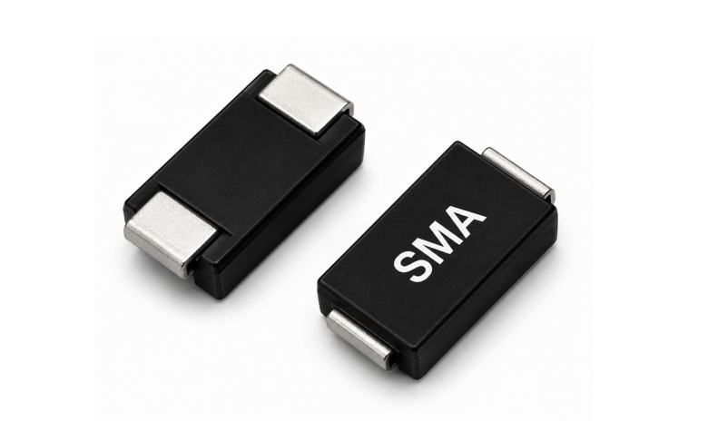
| SMA04J24V | SMA / DO-214AC | 24 V | 26.7 to 29.5 V | 38.9 V | 10.3 A | 400 W |
| SMB06J24V | SMB / DO-214AA | 24 V | 26.7 to 29.5 V | 38.9 V | 15.5 A | 600 W |
| SMC15J24V | SMC / DO-214AB | 24 V | 26.7 to 29.5 V | 38.9 V | 38.6 A | 1500 W |
These rows are useful for explaining a screening process. They do not prove that one device is a drop-in replacement for another. A larger package changes the land pattern, thermal path, board area, and specified current point.
Matching VRWM is only the first electrical filter
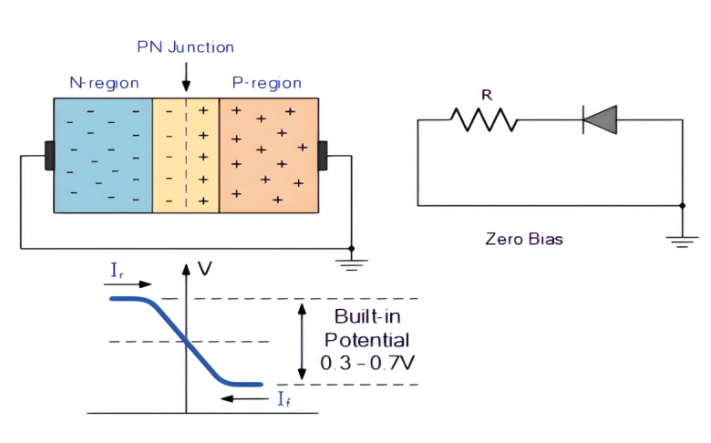
VRWM must remain above the highest continuous voltage, including tolerance, charging, ripple, and allowed steady abnormal states. The replacement also needs an acceptable breakdown and clamp window.
Check that:
VBR does not overlap the normal operating range;
maximum VC is read with the associated IPP and waveform;
board inductance and package inductance do not raise the protected-pin voltage beyond its limit;
reverse leakage remains acceptable at the required voltage and temperature;
the polarity construction fits both normal and fault behavior;
the temperature derating and pulse repetition conditions fit the application.
A lower catalog VC is not automatically better when the two values were measured at different currents.
Why the suffix cannot be omitted
Suffixes may identify polarity, tolerance, package, or construction. A procurement record that stores only the family name can lose the difference between a unidirectional and a bidirectional device.
On a positive DC input, a unidirectional TVS and a bidirectional TVS can behave differently during a negative event. Similar positive breakdown data therefore do not establish interchangeability.
Build a conditioned comparison table
| Review field | Original device | ASIM candidate | Approval rule |
|---|---|---|---|
| Full part number | Required | Required | Preserve all suffixes |
| VRWM | Data-sheet value | Data-sheet value | Covers maximum continuous voltage |
| VBR | Minimum and maximum | Minimum and maximum | Include test current |
| VC and IPP | Store as a pair | Store as a pair | Compare waveform and temperature |
| Polarity | Uni- or bidirectional | Uni- or bidirectional | Fit normal and fault polarity |
| Package | Drawing and land pattern | Drawing and land pattern | Verify dimensions and assembly |
| IR | Voltage and temperature | Voltage and temperature | Do not compare bare microamp values |
| Qualification evidence | Exact scope | Exact scope | Match part number and intended use |
Any mismatch needs an impact statement and a verification plan. It should not be hidden by a general claim that the candidate has a “higher rating.”
Board validation for a replacement candidate
Use the same PCB revision, cable, load, operating mode, and test setup for the baseline and candidate. Record:
normal startup, shutdown, hot-plug, and high-temperature behavior;
standby current, leakage, and device temperature;
voltage at the TVS and at the protected IC pin during the target pulse;
positive and negative pulse results at the required repetition interval;
leakage and functionality after stress;
A/B/A comparison with identified sample lots;
placement, reflow, AOI, and rework results.
Powering up successfully does not validate surge protection. Measuring only at the TVS terminals can also miss overshoot between the protection device and the protected IC.
Conditions that stop a cross-reference decision
the original suffix or current data sheet is unavailable;
the highest continuous circuit voltage has not been measured;
the original and candidate use different pulse waveforms without additional test data;
the protected-node absolute limit is unknown;
the footprint appears compatible but polarity or land pattern is different;
the only source is a distributor summary rather than current manufacturer documentation.
The correct action is to close the missing evidence, not to guess a replacement.
How ASIM documentation supports the process
ASIM data sheets place VRWM, VBR, VC, IPP, leakage, waveform, and package information in part-level documents. That structure supports a traceable cross-reference table. It does not remove the need to test the actual sample lot and PCB current path.
Frequently asked questions
Can SMA04J24V replace any 24 V SMA TVS?
No. The original polarity, breakdown range, clamp condition, waveform, leakage, land pattern, and protected-node limit must match.
Can a higher-power SMC part automatically replace an SMA part?
No. The footprint and assembly are different, and a higher peak-power class does not prove the required clamp behavior under an arbitrary waveform.
Is a third-party cross-reference table sufficient for release?
It can identify candidates. Release should use current data sheets from both manufacturers and measured results from the target product.
 Previous