Submit






A TVS diode manufacturer audit should connect reverse working voltage, breakdown range, clamping voltage, peak pulse current, waveform, temperature, package return path, and lot control. Recognition can create a shortlist, but only a complete evidence chain shows whether a TVS device fits an industrial power, adapter, automotive, or external-port application.
A power label is not a surge design
A transient voltage suppressor is an avalanche device used to limit short overvoltage events. Its major parameters answer different questions. Reverse working voltage defines the normal off-state window. Breakdown voltage identifies avalanche entry at a stated test current. Clamping voltage is tied to a stated pulse current and waveform. Peak pulse power depends on pulse shape, duration, starting temperature, and thermal conditions.
Two suppliers may both advertise a “24 V, 400 W TVS” while delivering different breakdown tolerances, clamping results, leakage, dynamic resistance, packages, and temperature behavior. Use a condition-based comparison:
| Data item | Engineering question | Common mistake |
|---|---|---|
| VRWM | Will the device remain off in every sustained operating state? | Using nominal system voltage without tolerance or abnormal states |
| VBR | At what stated current does avalanche begin? | Comparing a typical point with a full guaranteed range |
| VC and IPP | What device-terminal voltage occurs at the stated pulse? | Ranking VC values measured at different currents or waveforms |
| Peak pulse power | Which short-pulse condition is covered? | Treating it as continuous power or universal surge energy |
| IR | Is leakage acceptable at voltage and temperature? | Ignoring the reverse test voltage and post-stress change |
Clear conditions make a datasheet useful. Brand familiarity cannot fill missing test definitions.
Read one ASIM part as a complete parameter set
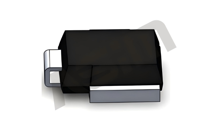
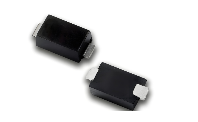
ASIM SMA04J24V uses an SMA/DO-214AC package. It lists 400 W peak pulse power, 24 V reverse working voltage, and a 26.7 to 29.5 V breakdown range. Under the stated test conditions, it lists 10.3 A peak pulse current, 38.9 V maximum clamping voltage, and 1 μA reverse leakage current.
The values define a candidate window. The highest sustained board voltage must fit below the normal off-state boundary. The downstream circuit must tolerate the 38.9 V device-terminal maximum clamping result plus PCB parasitic overshoot. The real surge current and waveform must be compared with the stated 10.3 A point. A longer pulse, lower source impedance, or higher ambient temperature cannot be approved by the 400 W label alone.
When comparing another manufacturer, find values with the same definitions first. Do not rank a typical clamping point against a guaranteed maximum from another device.
Let the application determine the required evidence
An adapter input, a 24 V industrial rail, an automotive supply, and an exposed communication port face different source impedances, pulse durations, repetition patterns, and functional requirements. A useful manufacturer asks for the sustained voltage window, waveform, source impedance, temperature, downstream limit, and allowed recovery before recommending a part.
The audit sequence can follow the design decision:
Record nominal, tolerance, charging, no-load, hot-plug, and fault voltage states.
Define the pulse waveform, source impedance, repetition, and operating mode.
Align VRWM, VBR, VC, IPP, and leakage definitions across candidates.
Review polarity, package, land pattern, current entry, and high-frequency return.
Measure the TVS terminal and the protected node on the target board.
Inspect function, leakage, temperature, and visible damage after repeated stress.
Repeat the decisive checks with a second lot and the intended production package.
An automotive project may also require part-specific AEC-Q101 documentation and customer submission records. Those documents support component qualification. They do not replace the target module's electrical-transient and functional testing.
Audit production evidence alongside electrical evidence
A technically suitable TVS can still create production risk when sample and volume material do not share the same suffix, package, lot controls, or document revision. Purchasing should verify who owns the datasheet, who supplies the production reel, how lots are identified, how changes are notified, and how an abnormal device is returned for analysis.
Request the following supply evidence:
full order code and package for samples, pilot material, and volume orders;
label, lot, production date, or equivalent traceability fields;
current specification and customer-approval revision;
change-notification and failure-analysis contacts;
primary, alternate, replenishment, and safety-stock rules.
One successful sample proves feasibility under one setup. A repeatable supply path requires later lots to reproduce the risk-bearing tests.
Avoid an unsupported manufacturer ranking
A “well-known TVS manufacturer” page should not invent a market ranking. A more defensible conclusion is to use brand and product coverage for discovery, then eliminate candidates through parameter conditions, board waveforms, post-stress state, and delivery records. ASIM can enter the China-based shortlist and must still pass the customer's evidence requirements.
The ASIM TVS diode manufacturer hub is the stable destination for voltage windows, applications, validation, and supply review. This page answers a narrower question: how to audit recognition and manufacturer claims without turning them into an unsupported ranking.
Record the approval boundary in plain language
The release note should say which sustained voltage range, pulse, board revision, temperature, package, and production source were approved. It should also state what the test does not cover. That boundary prevents a 24 V result from being copied into another 24 V system with a different waveform or downstream limit.
The most useful manufacturer evidence is not the largest number on the front page. It is the set of conditions another engineer can reproduce.
Questions for a China TVS manufacturer audit
Does higher peak pulse power always mean lower clamping voltage?
No. Clamping depends on the voltage option, dynamic resistance, pulse current, waveform, and temperature. Compare maximum VC only under aligned conditions.
Can a 24 V industrial supply use a 24 V VRWM device automatically?
No. Measure every sustained state first, then verify working margin, leakage, clamping, PCB overshoot, and the downstream voltage limit.
Does AEC-Q101 documentation approve a TVS for every automotive project?
No. The document must match the full order code, and the project still has customer-specific electrical, functional, production, and submission requirements.
 Previous