Submit






An IP camera needs port-specific ESD protection. Ethernet pairs, PoE or DC power, RS-485 control, a MicroSD socket, audio connections, and exposed buttons operate at different voltages and bandwidths. A valid selection starts with the port, protected IC, and current path, then reviews VRWM, capacitance, clamp conditions, channel topology, and PCB return.
Direct answer: prioritize low capacitance, channel matching, and S-parameters on high-speed differential lines. Prioritize the highest continuous voltage and VC at a stated pulse point on power and industrial-control lines. Review leakage and bias on storage-card, audio, and button nodes. Long outdoor cables may add surge requirements that cannot be inferred from a device-level IEC 61000-4-2 rating.
Build a port inventory before selecting parts
| Port | Function | First electrical constraint | Common review gap |
|---|---|---|---|
| RJ45 data pairs | Ethernet traffic | capacitance, differential/common-mode structure, magnetics position | cable-side and PHY-side parts mixed together |
| PoE or DC input | camera power | highest continuous voltage, VC, pulse current | insertion and surge treated as the same event |
| RS-485 | pan/tilt or external control | bus common-mode range, bidirectional structure, VC | long return path to the protection reference |
| MicroSD | local recording | 3.3 V window, Cj, channel count | socket shell has no short discharge path |
| Audio I/O | microphone or speaker | bias, leakage and audio loading | audio ground coupled into digital ground |
| Reset or pairing key | user input | leakage, RC timing and clamp window | added filter changes long-press detection |
Also identify which connectors are actually user accessible. Internal short traces and exposed external cables do not have the same threat model.
Why must Ethernet data and PoE power be reviewed separately?
Ethernet data reach the PHY through magnetics. The discharge and surge paths depend on the connector shell, center taps, magnetics, common-mode components, and chassis connection. A cable-side suppressor and a PHY-side low-capacitance ESD device therefore see different normal voltages and parasitic limits.
PoE adds a power path with its own detection, start-up, and continuous-voltage requirements. A 3.3 V device suitable for a PHY-side signal cannot be moved to a PoE supply conductor simply because both conductors enter the same RJ45 connector.
TI's industrial Ethernet EMC report emphasizes connector-side filtering, local decoupling, short and wide power connections, and a continuous return structure. These physical conditions remain necessary after a protection part has been selected.
Record six Ethernet details
Shielded or unshielded cable and connector construction.
Magnetics location and center-tap connections.
Whether the candidate is on the cable or PHY side.
Differential insertion loss and return-loss impact.
Shell, chassis, and digital-ground connection strategy.
Whether power and data share any part of the protection return.
What does an RS-485 protection review require?
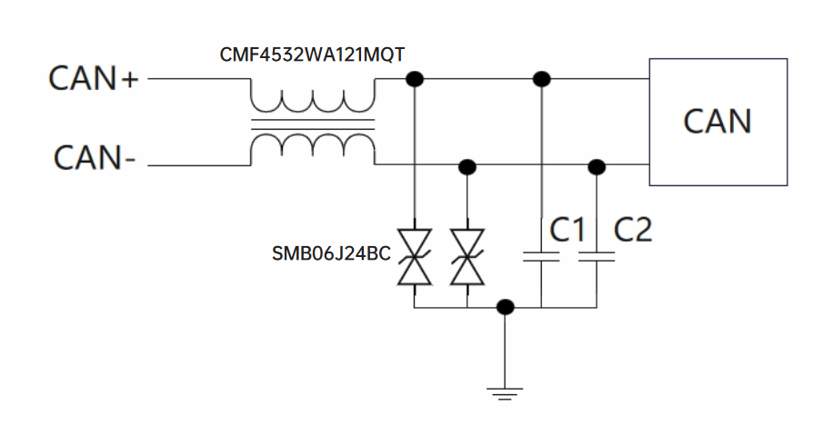
RS-485 is a bidirectional differential bus. Its permitted common-mode and fault conditions can exceed MCU GPIO levels. Measure or define the actual A/B operating window, then compare it with the candidate VRWM. Compare VC at the stated current and waveform with the transceiver pin limit.
TI's TIDA-00730 reference design evaluates TVS structures and pulse-proof resistor locations against IEC ESD, EFT, and surge on an RS-485 bus. The design illustrates why the three phenomena need separate conditions and records. A single “ESD-rated” statement does not establish EFT or surge performance.
How should a MicroSD socket be handled?
During card insertion, a user can contact the socket shell or card contacts. The clock and data lines need controlled capacitance and short branches. The supply line needs a compatible working voltage and low enough leakage. A socket shell tied to digital ground through a long trace can carry discharge current through the processor area.
A practical layout sequence is:
provide a short shell-discharge path;
place the ESD device at the first PCB entry from the contacts;
verify the pin order and common terminal of any array;
keep clock and data paths short and consistent;
repeat read, write, hot-insertion, and highest-speed mode checks.
How are ESD and cable surge kept separate?
IEC 61000-4-2 defines a system-level test for electrostatic discharge from personnel or nearby objects. Cable-induced surge uses other generators, waveforms, source impedances, and coupling methods. A review table should name the test method, waveform, source condition, coupling path, port, and pass criterion.
For the power path, record:
the highest continuous and permitted abnormal voltage;
the absolute maximum rating of the PoE front end or DC/DC stage;
VC together with IPP and waveform;
coordination with fusing, limiting, or upstream protection;
indoor or outdoor installation and cable length.
How can published ASIM data be used without overclaiming?
The ASIM ESD3V3D500TA Rev1.1 data sheet lists ±3.3 V VRWM, 50 pF typical capacitance, 6.5 V maximum VC at 1 A, and 12.5 V maximum VC at 33 A, with the clamp points stated for an 8/20 μs pulse. These values are useful for showing how a low-speed 3.3 V node should be reviewed. The 50 pF value also shows why a strong ESD headline cannot by itself qualify a part for a high-speed Ethernet pair.
The public ESD5E001TA page lists 0.08 pF typical capacitance in DFN0603-2L, making it a traceable low-loading screening example. ESD24R300TA Rev1.2 lists ±24 V VRWM and 36 V at 1 A plus 48 V at 8 A for 8/20 μs clamp points. It illustrates a higher-voltage control-line window. None of these examples replaces port measurement and board validation.
Frequently asked questions
Can an ordinary 24 V ESD diode be used on Ethernet pairs?
Voltage alone is insufficient. Differential bandwidth, junction capacitance, channel structure, magnetics position, and S-parameters must also fit the implementation.
Can PoE and a 12 V DC input share one TVS part?
Do not assume so. Their continuous voltage, start-up behavior, protected-stage limit, and surge conditions can differ.
Can surge review be skipped for an indoor camera?
Not solely because the product is indoors. Cable length, installation environment, power architecture, and the applicable product standard determine the required tests.
 Previous