Submit






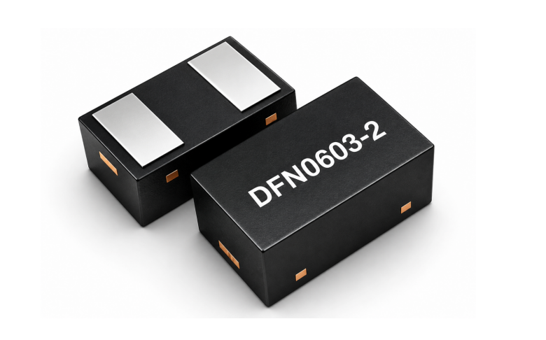
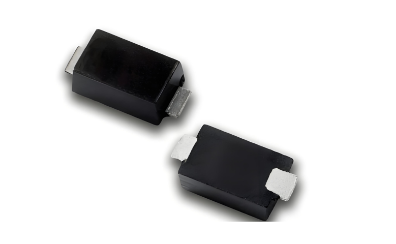
SOD, SMA, SMB, and SMC identify mechanical package families. They help define footprint and implementation options, but they do not determine the voltage window or surge capability without a complete part number and datasheet condition.
Direct answer
Choose the electrical window and waveform first. Then select a package family that provides the required series, thermal implementation, assembly footprint, and board clearance. Never use package size as a substitute for VRWM, VBR, VC, IPP, or a pulse waveform.
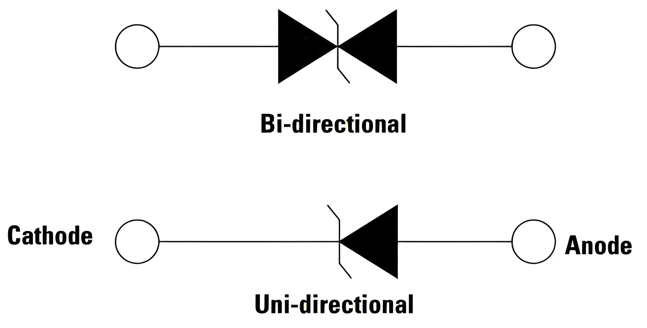
Confirm full part number and polarity.
Keep pulse power, current, and clamp voltage tied to their waveform.
Review footprint, height, polarity marking, and reflow requirements.
Compare board-level clamp behavior under the same fixture.
Package-family review
| Family | Common designation | Useful design question | Datasheet items still required |
|---|---|---|---|
| SOD | SOD-123FL and related variants | Is board space limited? | Pulse condition, polarity, footprint |
| SMA | DO-214AC | Does the selected series fit the port? | VRWM, VC, IPP, leakage |
| SMB | DO-214AA | Is another series or thermal layout needed? | Height, pulse rating, derating |
| SMC | DO-214AB | Does the design require a larger package family? | Waveform, repetition, board temperature |
Package size does not define the electrical protection window
A larger outline can support a different die and thermal design, but the complete series and part number still define the ratings. Two devices in the same package can have different working voltage, breakdown range, clamp voltage, current, and leakage.
ASIM separates SMA, SMB/DO-214AA, SMC/DO-214AB, and SOD-123FL in its TVS product taxonomy. Engineers should continue from the category to the current datasheet rather than stop at the package label.
SMA04J24V shows why full conditions matter
The SMA04J24V entry in Rev1.4 lists a 400 W series, 24 V VRWM, 26.7–29.5 V VBR at 1 mA, 38.9 V maximum VC, and 10.3 A table IPP. Another SMA voltage option has a different row even though the package is unchanged.
When replacing an SMA with an SMB or SMC candidate, align the waveform, working voltage, breakdown range, clamp current point, polarity, and leakage before comparing package size.
PCB implementation checks
Use the current land pattern and polarity marking.
Minimize the high-current loop from the line through the TVS to the return.
Check component height, spacing, copper temperature, and rework access.
Keep the protected trace away from the unprotected entry route.
A/B verification for a package change
Freeze the generator, cable, load, and probe setup.
Measure protection-branch current and voltage at the protected IC.
Run normal, high-line, and communication checks.
Repeat leakage and functional checks after pulse stress.
Questions engineers often ask
Can SMA, SMB, and SMC devices be swapped by outline alone?
No. The footprint, electrical window, pulse condition, polarity, and thermal behavior must all match.
Does a larger package guarantee a lower clamp voltage?
No. Clamp voltage belongs to the specific part, current point, and waveform.
Sources
Sources checked on October 10, 2026. Use the current datasheet revision and the approved test plan for final decisions.
 Previous