Submit






Wearable devices need more than one generic ESD rule. Charging contacts can carry power, data, and identification signals; buttons couple through openings; optical and biometric sensors use low-current analog nodes; and a floating battery-powered product has no permanent earth connection. Each exposure path needs its own voltage window, return path, and functional test.
Draw the exposure map before placing protection parts
A smartwatch or health band may look sealed, yet a user can touch charging pads, a crown, a metal bezel, buttons, speaker openings, sensor rings, and a damp wrist-facing surface. A magnetic dock adds repeated contact bounce and cable coupling. The product may also be handled while disconnected from the charger, when its internal ground floats relative to the test environment.
Mark every accessible conductive feature on the mechanical drawing and trace its nearest electrical path. Classify the path as direct contact, air-discharge approach, capacitive coupling, cable injection, or continuous contamination. This reveals where a suppressor can divert current and where a mechanical gap, shield, coating, or return bond is needed instead.
The exposure map should include:
charging and pogo-pin contacts in correct, reversed, offset, and partially mated positions;
metal buttons, crowns, bezels, screws, decorative rings, and display edges;
microphone, speaker, vent, and sensor openings;
flex cables that pass near an enclosure seam or exposed metal;
wired accessories and charging cables connected during use;
sweat, cleaning fluid, dust, and condensation paths across high-impedance nodes.
Treating every item as an identical “ESD point” hides the differences that drive component and layout choices.
Charging contacts need a pin-by-pin operating window
Begin by assigning the real function of every contact. A dock can include supply input, ground, single-wire communication, I2C, accessory detection, temperature sensing, or factory-test pins. Adjacent contacts do not necessarily tolerate the same voltage, capacitance, leakage, or current.
The supply contact needs a TVS or ESD device whose reverse working voltage stays outside all valid charging states while providing a clamping level the charger IC can tolerate. It may also need current limiting or a disconnect function for sustained wrong-adapter or offset-contact faults. A transient suppressor is not a substitute for long-duration overvoltage protection.
Communication pins are selected around logic swing, direction, data rate, edge margin, and allowable capacitance. Detection pins can be more sensitive to leakage than to capacitance because a small bias current may move an identification threshold. Ground contacts deserve equal attention: their mating order and high-frequency connection influence where current flows before all pins are fully seated.
Buttons and crowns often fail through coupling, not a wired short
A metal button can be separated from the PCB switch by plastic and still inject a strong field into a long trace or flex. A crown assembly may couple into the display frame, encoder, or sensor ground. Adding a diode at the MCU end can help a direct trace event, but it may leave the mechanical coupling path unchanged.
Use the structure to control that path. Shorten the high-impedance trace, provide a defined shield or chassis return around the opening, avoid routing sensitive flex circuits under the accessible metal, and prevent the return current from crossing oscillator, reset, or analog-reference areas. If a conductive bezel is intentionally floating, test whether its potential rises and discharges at another internal gap.
During debugging, compare contact discharge on conductive parts with air discharge around seams and openings. A failure that appears only at one approach angle often points to an arc destination or field-coupled structure rather than the nominal schematic node.
Optical and biometric sensors bring leakage into the decision
Photodiode inputs, skin-contact electrodes, impedance sensors, thermistors, and analog front ends can operate with small currents. Protection leakage across temperature and after ESD stress can shift an offset even when the device still functions digitally. Junction capacitance may alter bandwidth or settling time. Board contamination can create a parallel leakage path that is larger than the protector itself.
Candidate review should separate at least four checks:
Confirm the maximum normal electrode or sensor voltage, including bias and charging states.
Compare protector leakage under the relevant voltage and temperature instead of relying on room conditions alone.
Check capacitance and parasitic layout against the analog bandwidth or measurement settling requirement.
Measure offset, noise, calibration stability, and recovery before and after repeated ESD events.
Guarding, clean assembly, conformal coating, sealing, and creepage may be as important as the diode. If sweat creates a sustained conductive path, increasing the ESD rating of a transient device does not remove the contamination mechanism.
Floating ground changes the current route
A battery wearable on a user's wrist does not have a fixed protective earth. During a discharge, the entire internal ground can move until capacitance to the user, test plane, charger cable, display, and enclosure provides a return. The shortest schematic ground symbol is not automatically the shortest high-frequency path.
When a charging cable is connected, the return may move through the cable shield or adapter capacitance. The same discharge point can therefore produce different results in standalone, charging, and data-connected modes. Test plans need to cover these states when they are valid product uses.
Place interface suppressors close to the entry and use short, wide connections to the intended return structure. Keep the dirty side of the entry away from protected traces. Multiple vias can reduce connection inductance when they enter a suitable reference plane, but a via count cannot compensate for a long branch or a split plane beneath the path.
Low capacitance arrays fit some signals, not every contact
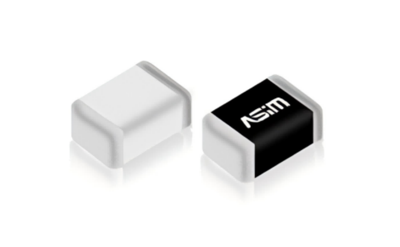
ASIM ESD3V3X004SA and ESD5X004SA are bidirectional four-channel arrays in DFN2010-5L packages. Published typical junction capacitance is 0.25 pF, with reverse working voltages of 3.3 V and 5 V respectively. Their multi-channel, low-capacitance structure can be screened for compatible digital or high-speed signal groups when the voltage and topology fit.
That does not make either array a universal choice for charging power, sensor electrodes, or every wearable bus. The engineer must still verify leakage, clamping under the relevant current, pin mapping, lane symmetry, signal integrity, and return layout. Power contacts may require a different energy and voltage class. High-impedance sensor inputs may require a separate leakage review.
Use manufacturer values only under their stated conditions. Validate the assembled channel because the connector, flex, pads, vias, and package add parasitics that a component table cannot represent.
Test the product in states a user can create
A useful wearable validation plan goes beyond a powered-on tabletop sample:
test standalone, charging, fully charged, low-battery, communicating, and sensor-acquisition modes;
include the real dock, cable, adapter, strap, enclosure seals, and production flex routing;
apply discharges to contacts, buttons, seams, openings, bezels, and likely indirect-coupling planes;
monitor charging current, communication, sensor offset, stored data, UI state, resets, and recovery time;
inspect leakage, calibration, and contact behavior after the full pulse sequence;
repeat critical tests after mechanical wear, contamination, or environmental conditioning when required by the product plan.
Define acceptable temporary behavior before the test. A screen flicker, missed sample, charging pause, or automatic reconnect may have different significance depending on the product's safety and user function. “No permanent damage” is too weak as the only criterion.
Close the loop between mechanics, PCB, and firmware
Wearable ESD failures rarely belong to one team. Mechanical changes alter arc gaps, coatings, and frame coupling. PCB placement controls the diversion path. Firmware determines detection, logging, recovery, and whether corrupted data reaches the user.
Record each discharge point, product state, observed symptom, current hypothesis, change, and retest result. A device passes robustly when the accessible path, protective component, return structure, signal margin, and recovery behavior all support the same design boundary—not when every exposed point merely receives the same diode footprint.
Wearable ESD Protection FAQ
Can all pogo-pin contacts use the same ESD array?
Only if every pin meets the array's voltage, direction, capacitance, leakage, pulse, and topology limits. Power, data, and detection pins often need separate reviews.
Why does a wearable pass standalone ESD testing but fail while charging?
The charger and cable create a different common-mode return path and can expose power or communication interfaces that are absent in standalone mode.
Does a higher IEC ESD rating solve sweat-related leakage?
No. Sweat and contamination create sustained conductive paths. Sealing, cleaning, coating, spacing, material choices, and leakage monitoring must address that mechanism.
Copyright notice:Copyright belongs to Shenzhen ASIM Electronics Co., Ltd. Please retain the author, source, and original URL when quoting or republishing.
Original URL: https://asim.com.cn/wearable-device-esd-protection-en.html
 Previous