





 Submit


ESD Protection for Gigabit and 2.5G Ethernet Ports: Line-Side and PHY-Side Complete Design Guide
 2026.06.15 00:00:00
 248
248





Gigabit Ethernet (1000BASE-T) and 2.5G Ethernet (2.5GBASE-T) ports require ESD protection at two distinct locations: the line side (between the RJ45 connector and the network transformer) and the PHY side (between the network transformer and the PHY chip). The protection components differ significantly between these two positions — the line-side TVS handles high-energy transients while the PHY-side ESD diode must have capacitance below 0.5 pF to preserve signal integrity at 125 MHz or 312.5 MHz.
This guide provides specific ASIM part numbers, placement rules, and the rationale for selecting different components at each position.
Why Are Two Different Protection Approaches Needed for Ethernet?
The network transformer (also called a LAN transformer or magnetics module) creates an impedance break in the circuit. The transformer has several important properties:
1. It provides galvanic isolation between the cable and the PHY chip
2. It has built-in common mode rejection (typically 40–60 dB at the signal frequency)
3. It has low-pass characteristics that attenuate high-frequency transients
However, the transformer does not protect against:
· Low-frequency transient energy that passes through the transformer's coupling
· High-energy surges from lightning-induced transients on long cable runs
· ESD entering through parasitic coupling across the transformer windings
This is why protection is required on both sides of the transformer.
What Components Protect the Line Side (Between RJ45 and Transformer)?
The line side faces cable-level transients including ESD from cable plug insertion, lightning-induced surges from long cable runs, and EFT interference from industrial environments.
Line-side requirements:
· Must absorb surge energy: IEC 61000-4-5 Level 3 produces 1–2 kV transients
· Capacitance is not critical: the transformer filters capacitive loading effects
· Bidirectional: differential signal swings both positive and negative
Recommended ASIM components for line side:
Application | Part Number | PPM | VRWM | Notes |
Indoor installation | SMA04J05B | 400 W | 5 V | Bidirectional, SMA package |
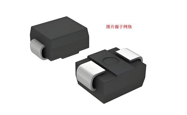
Industrial / outdoor | SMB06J05B | 600 W | 5 V | Bidirectional, SMB package |
High-lightning area | SMCJ05B | 1,500 W | 5 V | Bidirectional, SMC package |
Place one component per differential pair: four TVS diodes total for 1000BASE-T (four pairs), connected between each line and the ground plane.
Connection:
RJ45 Pin 1 (TX+) ──┬── [SMA04J05B cathode] ── GND
RJ45 Pin 2 (TX-) ──┘ (shared TVS for differential pair)
RJ45 Pin 3 (RX+) ──┬── [SMA04J05B cathode] ── GND
RJ45 Pin 6 (RX-) ──┘
(Repeat for remaining two pairs in 1000BASE-T)
For each differential pair, either one TVS per line (two TVS for the pair) or one TVS between the pair midpoint and ground. The two-TVS configuration provides better differential protection.
What Components Protect the PHY Side (Between Transformer and PHY Chip)?
The PHY side is where signal integrity constraints drive component selection. 1000BASE-T PHY chips receive signals at 125 MHz (symbol rate). 2.5GBASE-T operates at 312.5 MHz. Any capacitance on the PHY-side signal lines causes signal attenuation and return loss that degrades link quality.
PHY-side requirements:
· Capacitance: ≤ 0.5 pF per line for Gigabit Ethernet, ≤ 0.3 pF for 2.5G
· Low leakage current: the transformer output is high-impedance; leakage disturbs the DC common mode
· Bidirectional: Ethernet differential signal is AC-coupled through the transformer
Recommended ASIM components for PHY side:
Interface | Part Number | Cj | VRWM | Package |
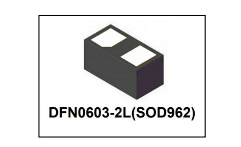
1000BASE-T (PHY side) | ESD5E002TA | 0.18 pF | 5 V | DFN0603-2L |
2.5GBASE-T (PHY side) | ESD3V3E003TA | 0.30 pF | 3.3 V | DFN0603-2L |
100BASE-TX (PHY side) | DFN1006-2L (5V) | ≤ 1.0 pF | 5 V | DFN1006-2L |
The ESD5E002TA (Cj = 0.18 pF) does not meaningfully affect 125 MHz signal integrity. At 125 MHz, 0.18 pF presents an impedance of approximately 7,000 Ω — far higher than the 100 Ω differential termination. Signal loss due to the ESD diode is negligible.
How Should Line-Side and PHY-Side Components Be Placed?
Line-side TVS placement:
RJ45 connector solder pads
│ (trace < 10 mm)
TVS diodes (SMA04J05B or SMB06J05B)
│
GND via (< 5 mm from TVS pad)
│
Network transformer (RJ45 or discrete magnetics)
The TVS diodes go between the RJ45 connector and the transformer input. GND return should connect to the chassis ground (protective earth), not the signal ground of the PHY. This provides a discharge path that does not contaminate the signal ground plane.
PHY-side ESD diode placement:
Network transformer output
│ (trace < 5 mm)
ESD diode (ESD5E002TA)
│
GND via (< 1 mm from ESD pad)
│
PHY chip MDI pins
The PHY-side ESD diodes are placed as close to the PHY chip MDI input pins as possible. This minimizes the trace length between the last protection element and the sensitive IC input. Longer traces between the ESD diode and the PHY create additional parasitic inductance that reduces protection effectiveness.
Complete Protection Circuit for a Gigabit Ethernet Port
RJ45 Connector (4 differential pairs)
│
[Line-side TVS: SMA04J05B × 4] ← bidirectional, one per pair
│
Ethernet Network Transformer
(with integrated common mode choke, 1:1 ratio, IEEE 802.3 spec)
│
[PHY-side ESD: ASIM ESD5E002TA × 4] ← 0.18 pF, one per pair
[PHY-side CMC: ASIM CMF1210UD101MST × 4] ← 100 Ω @ 100 MHz
│
Gigabit PHY Chip (RTL8211, BCM54210, Intel I226, etc.)
The CMF1210UD101MST common mode choke on the PHY side provides additional common mode rejection for conducted interference that passes through the transformer. This is particularly useful in industrial environments where the transformer's common mode rejection (40–60 dB) may be insufficient against high-amplitude VFD or welding interference.
Selecting Between SMA04J05B and SMB06J05B for Line-Side Protection
Both parts have VRWM = 5 V and clamping voltage VC max = 9.72 V. The difference is peak pulse power rating:
Parameter | SMA04J05B | SMB06J05B |
PPM (1 ms) | 400 W | 600 W |
IPP (8/20 µs) | ~17 A | ~25 A |
Package | SMA (4.4 × 2.7 mm) | SMB (5.3 × 3.7 mm) |
IEC 61000-4-5 Level | Level 3 (±2 kV) | Level 4 (±4 kV) |
Use SMA04J05B for office or home network equipment (typical indoor installation). Use SMB06J05B for industrial switches, industrial IP cameras, outdoor network equipment, or equipment installed in environments with other high-power equipment (motors, welding, large HVAC).
Frequently Asked Questions
Q: Does a built-in RJ45 connector with integrated magnetics (also called "RJ45 with magnetics" or "MagJack") still need external line-side TVS protection?
A: Yes. Built-in magnetics provide the isolation transformer function but do not include surge protection components. The connector still requires TVS diodes between its external pins and the transformer/magnetics. The PHY-side ESD diodes are still needed between the magnetics output and the PHY chip.
Q: After adding ESD5E002TA (0.18 pF) on the PHY side, the Gigabit link occasionally negotiates down to 100 Mbps. What is wrong?
A: The ESD5E002TA capacitance alone (0.18 pF) should not cause this. More likely causes: the common mode choke (CMF1210UD101MST) differential mode inductance is loading the 125 MHz signal, or the ESD diode GND connection is creating a reference imbalance between the four pairs. Verify that all four pairs have identical ESD diode placement and matched GND trace lengths.
Q: Is GDT (gas discharge tube) needed in addition to the line-side TVS for outdoor installations?
A: For outdoor runs exposed to direct lightning risk (e.g., rooftop cameras, outdoor switches, inter-building links), a three-stage approach is recommended: GDT (primary, 90 V strike voltage) → TVS (secondary, SMB06J05B, 600 W) → PHY-side ESD (ESD5E002TA). For indoor installations in commercial buildings, the TVS alone (SMA04J05B or SMB06J05B) is typically sufficient for IEC 61000-4-5 Level 3 compliance.
About ASIM Electronics: ASIM (阿赛姆电子) is a Shenzhen-based manufacturer of ESD and TVS protection components, founded in 2013. Ethernet protection product line: SMA04J05B (400 W, line-side), SMB06J05B (600 W, industrial), ESD5E002TA (0.18 pF, Gigabit PHY side), ESD3V3E003TA (0.30 pF, 2.5G PHY side), CMF1210UD101MST (100 Ω common mode choke). Contact: +86-400-014-4913 | asim@asim.com.cn | Published: June 2026
 Previous

Related News
2025.09.05
ESD5E001TA Bidirectional TVS Diode Technical Specification -ASIM
2025.09.06
TVS Diode Failure Mode Analysis: Design Guide for Protection Differences between Short Circuit and Open Circuit -ASIM
2025.09.08
High-frequency Circuit TVS Diode Junction Capacitance Optimization Strategy -ASIM
2026.05.19
What Is an ESD Diode? Working Principle, Key Parameters & Selection Guide
2026.06.10
ESD protection for the gate of SiC/GaN power devices: Why it is more difficult to protect than IGBT
2026.06.11
How Chinese ESD Manufacturers Match Global Standards: ASIM Technical Analysis
2026.06.12
ESD Protection for High-Speed Interfaces: Complete Design Guide for USB4, PCIe Gen5, HDMI 2.1, and Thunderbolt 4

2026.06.12
TVS Diode Selection Guide for 800V Electric Vehicle Systems: High-Voltage Platform Protection
2026.06.13
ESD Protection for Industrial Communication Buses: RS-485, CAN, Modbus, and Profibus Complete Guide
2026.06.13
Common Mode Inductor Selection for Wi-Fi Routers and Home Networking Equipment


