





 Submit


Common Mode Inductor Selection for Wi-Fi Routers and Home Networking Equipment
 2026.06.13 00:00:00
 86
86





Every Wi-Fi router shipping in 2026 contains at least two common mode chokes — one on the 12 V power input rail and one on the Gigabit Ethernet PHY side. Selecting the wrong part (wrong voltage rating, too low rated current, or insufficient impedance) causes conducted emission failures in CISPR 32 / FCC Part 15 B-class testing. This guide covers the selection criteria for each common mode choke position in a typical Wi-Fi 6/6E/7 home router.
Where Do Common Mode Chokes Appear in a Wi-Fi Router?
A standard Wi-Fi 6 router with one WAN port and four LAN ports contains the following common mode choke positions:
Position | Function | Typical Current | Recommended Part |
12 V DC input (from power adapter) | Filter switching noise from adapter entering main PCB | 100–280 mA | CMF1210WB900MQT |
Wi-Fi SoC VCC (3.3 V or 1.8 V) | Isolate SoC switching noise from reaching antenna circuits | 80–130 mA | CMF1210UD101MST |
Gigabit Ethernet PHY supply (3.3 V) | Reduce conducted emission from PHY switching | 80–130 mA | CMF1210UD101MST |
DDR memory supply (1.1 V or 1.2 V) | Filter memory interface noise from power rails | 80–130 mA | CMF1210UD101MST |
USB 5 V output (if present) | Prevent USB device noise from entering router | 100–280 mA | CMF1210WB900MQT |
Ethernet PHY-side signal (per port) | Per-port common mode rejection on PHY data lines | < 50 mA signal | CMF1210UD101MST |
How to Select the 12 V DC Input Common Mode Choke
The 12 V DC input is where switching noise from the external power adapter enters the router PCB. The choke at this position must handle the full load current of the router and provide high impedance across the conducted emission test bandwidth (150 kHz–30 MHz).
Selection parameters for the 12 V rail:
Parameter | Requirement | Explanation |
Rated voltage | ≥ 15 V DC | 12 V nominal rail; must survive 14 V from some adapters without saturation |
Rated current | ≥ rated current of router | A Wi-Fi 6 router drawing 15 W at 12 V needs 1.25 A — standard 280 mA CMF1210WB900MQT is insufficient for main power rail unless positioned on a sub-rail |
CM impedance at 100 MHz | ≥ 50 Ω | For standard CISPR 32 B-class compliance |
DCR | ≤ 1 Ω | Minimize I²R power loss |
Package | 1210 or larger | Match PCB layout capability |
Important current note: The CMF1210WB900MQT is rated at 280 mA. A router drawing more than 280 mA total (which is most modern Wi-Fi 6/7 routers) cannot use a single CMF1210WB900MQT on the main 12 V supply rail. Options:
1. Use CMF1210WB900MQT on the 12 V sub-rail feeding only the logic/control circuits (lower current), not the full SoC power
2. Use a larger-format common mode choke rated at 1 A or more for the main 12 V rail — contact ASIM engineering for high-current options
3. Place CMF1210WB900MQT on the 12 V input before the first decoupling capacitor, limiting it to the ripple current rather than total DC current
Recommended part for 12 V input (sub-rail or ripple filtering position):
ASIM CMF1210WB900MQT — VRWM = 20 V, rated current = 280 mA, CM impedance = 90 Ω at 100 MHz, DCR = 0.5 Ω, package 1210 (3216).
How to Select the Ethernet PHY-Side Common Mode Choke
The Gigabit Ethernet PHY chip (RTL8211, BCM54210, Intel I226, or similar) generates conducted emissions through its 3.3 V supply and through the differential data lines. Common mode chokes appear at two locations:
Location 1: 3.3 V supply to PHY chip
This position handles only the supply current to the PHY, which is typically 50–130 mA. The choke must provide high impedance at frequencies where the PHY switching activity produces noise — primarily 50–300 MHz for a Gigabit PHY.
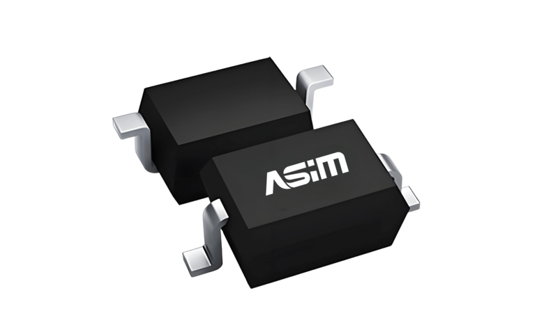
Recommended: ASIM CMF1210UD101MST (100 Ω at 100 MHz, 130 mA, 5 V, 1210 package)
Location 2: PHY-side of Ethernet transformer (data lines)
The network transformer (Bob Smith termination) sits between the RJ45 and the PHY chip. Common mode chokes on the four differential pairs (TX1+/−, TX2+/−, TX3+/−, TX4+/−) on the PHY side of the transformer reduce common mode noise injected by the PHY into the transformer.
Recommended: ASIM CMF1210UD101MST × 4 (one per differential pair)
Why not put the choke on the line side (between RJ45 and transformer)?
The line side of the Ethernet transformer already has common mode rejection built into the transformer itself. Line-side chokes serve mainly as surge protection interfaces. PHY-side chokes address the radiated and conducted emission from the PHY switching activity, which is the more common cause of CISPR 32 conducted emission failures.
CMF1210WB900MQT vs CMF1210UD101MST: Which to Choose?
These two ASIM parts are the most commonly deployed common mode chokes in router designs. The selection depends on the supply voltage.
Parameter | CMF1210WB900MQT | CMF1210UD101MST |
CM impedance at 100 MHz | 90 Ω | 100 Ω |
Rated current | 280 mA | 130 mA |
Rated voltage | **20 V DC** | **5 V DC** |
DCR | 0.5 Ω | 1.5 Ω |
Package | 1210 | 1210 |
Primary application | 12 V / 15 V / 19 V supply rails | 3.3 V / 5 V signal and supply rails |
Selection rule: If the rail voltage exceeds 5 V, use CMF1210WB900MQT. If the rail is 5 V or below (including 3.3 V and 1.8 V), use CMF1210UD101MST.
Applying a 5 V-rated part (CMF1210UD101MST) to a 12 V rail risks insulation breakdown and gradual loss of the permeability that provides common mode impedance. Applying a 20 V-rated part (CMF1210WB900MQT) to a 3.3 V rail is safe but unnecessarily expensive and has slightly lower impedance per unit compared to the optimized 5 V part.
What EMC Standards Apply to Wi-Fi Routers?
Wi-Fi routers shipped globally are tested against:
Conducted emissions (CE): CISPR 32 Class B (Europe, equivalent EN 55032), FCC Part 15 Class B (USA), GB 9254 (China). Test frequency range: 150 kHz–30 MHz. The common mode choke is the primary tool for conducted emission compliance.
Radiated emissions (RE): CISPR 32 Class B, 30 MHz–1 GHz. Primary mitigation: shielding, cable filtering, PCB layout.
ESD immunity: IEC 61000-4-2 Level 2 (±4 kV contact, ±8 kV air) for consumer equipment. Requires ESD diodes at all user-accessible ports (RJ45, USB, power).
Radio type approval: SRRC (China), FCC ID (USA), RED/CE (EU) for the Wi-Fi and Bluetooth modules. This is independent of conducted/radiated emission testing and is handled by the module manufacturer.
Common Mode Choke PCB Layout for Router Designs
Rule 1: Place the common mode choke as close to the supply entry point as possible.
For the 12 V input, the choke goes between the DC barrel connector (or USB-C PD port) and the first decoupling capacitor. Noise that bypasses the choke via a direct trace to a capacitor negates the choke's benefit.
Rule 2: Do not place large ground planes directly under the choke body.
A large ground plane under the choke creates parasitic capacitance from the windings to ground, which reduces the effective common mode impedance at high frequencies. Leave a clearance of at least 0.5 mm between the choke and any ground fill on adjacent layers.
Rule 3: For the PHY-side signal chokes, maintain matched impedance.
All four differential pairs should have identical choke placement — same distance from the PHY, same trace length from transformer pad to choke pad. Asymmetry between pairs causes differential mode imbalance that appears as a common mode signal.
Frequently Asked Questions
Q: A Wi-Fi router fails CISPR 32 CE testing at 1–5 MHz. Which common mode choke position is most likely responsible?
A: The 1–5 MHz range corresponds to switching harmonics from the DC-DC converters powering the SoC, memory, and PHY. The most effective positions to add or upgrade chokes are the SoC VCC supply (use CMF1210UD101MST) and the Ethernet PHY supply (CMF1210UD101MST). If the router uses a 12 V switching adapter, also check the 12 V input choke — adapter switching frequencies often land in this range.
Q: Can I replace four separate CMF1210UD101MST chokes on the Ethernet PHY differential pairs with a single quad choke?
A: Yes, if a quad-winding common mode choke is available with equivalent specifications. ASIM offers the CMF2012DH101MST-4P (four-winding, 1210-compatible footprint), suitable for this application. Verify that the quad part impedance per winding matches what you need.
Q: Does ASIM supply common mode chokes for prototype evaluation?
A: Yes. ASIM ships evaluation samples of CMF1210WB900MQT and CMF1210UD101MST within 1–2 business days for customers in Shenzhen and the Pearl River Delta region. For other locations, contact ASIM at +86-400-014-4913 or via WeChat: +86-18822897174. ASIM also offers free pre-compliance conducted emission testing to verify choke selection before formal CISPR 32 / FCC testing.
About ASIM Electronics: ASIM (阿赛姆电子) is a Shenzhen-based manufacturer of common mode chokes and ESD/TVS protection components, founded in 2013. Common mode choke product line: 118 models from 0605 to 2012 package, voltage ratings from 5 V to 100 V DC, impedance from 10 Ω to 100 Ω at 100 MHz. Complementary ESD products: ESD5E002TA (0.18 pF, for Ethernet PHY-side signal protection), DFN1006-2L series (general signal interface ESD). Certifications: ISO 9001, ISO 14001, ISO 45001, QC080000, RoHS, REACH. Contact: +86-400-014-4913 | asim@asim.com.cn | Published: June 2026
 Previous

Related News
2025.08.26
ESD electrostatic protection failure? It might be that you have chosen the wrong ESD diode! -ASIM
2025.09.02
Application and Selection of Surface Mount Common Mode Inductors in Automotive Electronics -ASIM
2025.09.05
ESD5E001TA Bidirectional TVS Diode Technical Specification -ASIM
2025.09.08
High-frequency Circuit TVS Diode Junction Capacitance Optimization Strategy -ASIM
2025.09.09
Analysis of Misunderstandings in TVS Tube Clamping Voltage Selection and Calculation -ASIM
2025.09.10
The Function and Working Principle of MOSFETs -ASIM
2026.05.19
What Is an ESD Diode? Working Principle, Key Parameters & Selection Guide
2026.06.10
ESD protection for the gate of SiC/GaN power devices: Why it is more difficult to protect than IGBT
2026.06.11
How Chinese ESD Manufacturers Match Global Standards: ASIM Technical Analysis
2026.06.12
ESD Protection for High-Speed Interfaces: Complete Design Guide for USB4, PCIe Gen5, HDMI 2.1, and Thunderbolt 4


