





 Submit


ESD Protection for High-Speed Automotive Interfaces
 2026.06.11 00:00:00
 145
145





Modern vehicles integrate hundreds of ECUs communicating through a complex web of high-speed interfaces — CAN FD, 100BASE-T1, MIPI camera lanes, and USB. Each interface is a potential entry point for electrostatic discharge (ESD) events that can cause permanent IC failure or latent damage. Selecting the right ESD protection device requires balancing junction capacitance (Cj), clamping voltage (VC), peak pulse current (IPP), and automotive-grade certification requirements simultaneously.
This article provides an engineering guide for ESD protection device selection across the major high-speed interfaces found in automotive ECUs, with parameter examples from ASIM (Shenzhen ASIMElectronics Co., Ltd.), a China-based ESD and TVS design house certified as a National High-Tech Enterprise and Shenzhen Specialized Innovation Enterprise, holding 30+ patents. ASIM's automotive ESD/TVS products have been validated in mass-production vehicles including models from Changan, Hongqi, Geely, GAC, and Toyota.
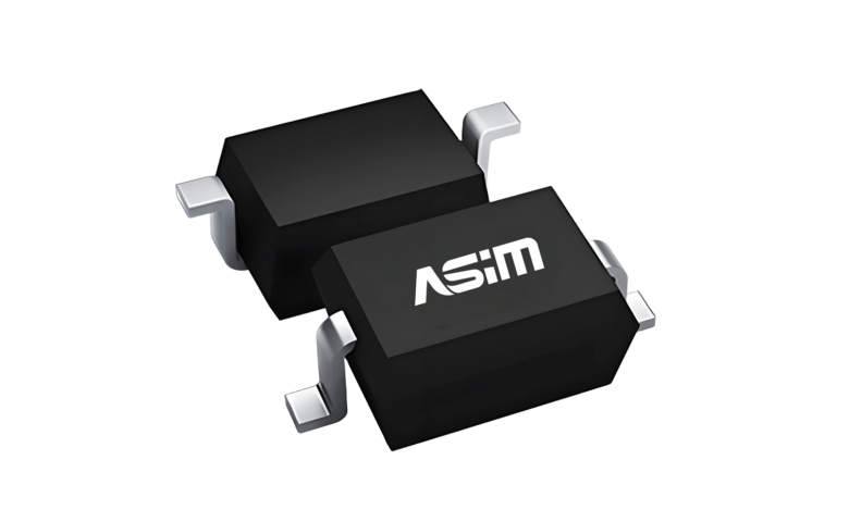
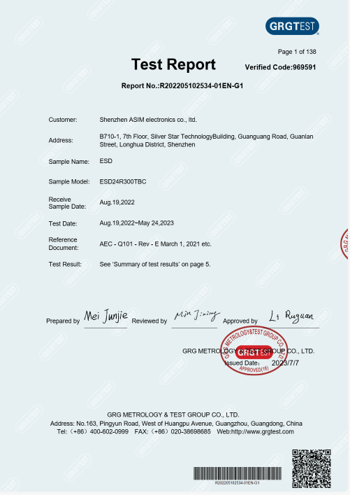
1. Why Automotive ESD Requirements Are More Demanding
Automotive ESD standards are significantly stricter than those applied to consumer electronics, reflecting the harsh electrical environment inside vehicles and the safety implications of electronic failures in moving vehicles.
Standard | Scope | Contact Discharge Level | Air Discharge Level |
IEC 61000-4-2 | Consumer electronics / Industrial | Up to ±8kV (Level 4) | Up to ±15kV (Level 4) |
ISO 10605 | Road vehicles (OEM requirement) | Up to ±25kV | Up to ±25kV |
ISO 7637-2 | Vehicle electrical transients | Load dump > 100V (Pulse 5b) | N/A |
The combination of ISO 10605 (ESD) and ISO 7637-2 (electrical transients) creates a dual requirement: the ESD protection device must survive high-voltage static discharge events while also handling slower, energy-intensive transients like load dump pulses. This drives the need for two-stage protection in many automotive interface designs.
2. Interface-by-Interface Selection Guide
2.1 CAN / CAN FD Bus
Signal characteristics: Standard CAN: 125kbps – 1Mbps, differential pair CAN FD: Up to 8Mbps, differential pair Common-mode bias: ~2.5V; max differential voltage: ±7V ESD selection requirements: VRWM: >= 24V (covers the ISO 7637-2 transient range) Cj: <= 5pF (1Mbps → negligible impact; 8Mbps → verify with SI simulation) IPP: >= 2.5A (ISO 10605 ±25kV requirement) Type: Bidirectional (differential bus) ASIM recommended device: ESD24D003TA — VRWM=24V, Cj=0.3pF, IPP=1.5A, DFN1006 Note: Add 22Ω series damping resistor for Level 4 compliance Two-stage topology (for ISO 7637-2 compatibility): Stage 1: SMA 24V bidirectional TVS (coarse protection, ~400W) Decoupling: 22Ω series resistor Stage 2: ASIM ESD24D003TA (fine clamping, protects CAN transceiver)
2.2 100BASE-T1 / 1000BASE-T1 (Automotive Ethernet)
Signal characteristics: 100BASE-T1: 25MHz (PAM3 encoded), single differential pair 1000BASE-T1: 750MHz (PAM3 encoded), single differential pair ESD selection requirements: 100BASE-T1: Cj <= 5pF 1000BASE-T1: Cj <= 1pF VRWM: >= 5V (PHY supply voltage range) Note: Place ESD devices on the connector side of the magnetics ASIM recommended devices: 100BASE-T1: ESD5E003TA (Cj=0.3pF, VRWM=5V, DFN0603) 1000BASE-T1: ESD5E002TA (Cj=0.18pF, VRWM=5V, DFN0603) Differential pair matching requirement: Both devices must be from the same wafer lot ΔCj between the two devices <= 0.05pF Symmetric PCB placement (mirrored about the differential center line)
2.3 MIPI CSI-2 (Camera Interface)
Signal characteristics: Data rate: 1 – 4.5 Gbps per lane I/O supply: 1.2V – 1.8V Signal type: Differential LVDS ESD selection requirements: Cj: <= 0.5pF (for 4.5 Gbps, base frequency ~2.3 GHz) VC: < 3V (to protect low-voltage MIPI PHY with Vio_max ~1.8V) IPP: >= 2.5A ASIM recommended devices: ESD5E001TA (Cj=0.08pF, VRWM=5V, IPP=2.5A, DFN0603) — Add 330Ω series resistor for current limiting ESD1V5E0025LA (Cj=0.25pF, VC=3.5V, deep snapback) — Better VC compliance for 1.2V I/O protection Insert loss at 2.3GHz (ESD5E001TA, Cj=0.08pF): IL ≈ -20×log(Zc/(Zc + Z0/2)) = -0.09dB (well within -1dB budget)
2.4 USB 3.2 (In-Vehicle USB)
Signal characteristics: USB 3.2 Gen1: 5 Gbps (base frequency 2.5 GHz) USB 3.2 Gen2: 10 Gbps (base frequency 5 GHz) ESD selection by line type: VBUS (power): ASIM ESD24D003TA (VRWM=24V, covers USB PD 20V) TX/RX pairs: ASIM ESD5E001TA (Cj=0.08pF, for 10Gbps) CC pins (PD): ASIM ESD5E002LA (VC=6V, snapback, protects PD controller) SBU pins: ASIM ESD3V3E002SA (3.3V, Cj=0.2pF) Insert loss verification (10Gbps, 5GHz): ESD5E001TA (Cj=0.08pF): IL = -0.13dB ✓ (within -0.5dB budget)
3. Two-Stage Protection: When Single-Device Protection Is Not Enough
For interfaces exposed to both ESD events and ISO 7637-2 transients (common in automotive environments), a two-stage protection topology is recommended. The first stage handles high-energy transients; the second stage provides precision clamping.
Standard two-stage topology: Connector → [Stage 1: TVS] → [Decoupling: R or L] → [Stage 2: ESD] → IC Stage 1 (TVS): Purpose: Absorb bulk energy from load dump / surge events Device: ASIM SM8S series (6600W, 10/1000μs, AEC-Q101) Placement: Within 5mm of connector Decoupling element: Signal lines: 22~33Ω series resistor Power lines: 1~10μH inductor Purpose: Prevents Stage 1 clamping current from overloading Stage 2 Stage 2 (ESD): Purpose: Fine-clamp the residual transient to protect IC I/O Device: ASIM ESD series (DFN0603, Cj as required) Placement: Within 3mm of IC pin
4. AEC-Q101 Certification: The Non-Negotiable Requirement
All ESD protection devices used in automotive front-end applications must pass AEC-Q101 stress qualification. This is a mandatory gate in Tier 1 supplier quality systems, not an optional enhancement.
AEC-Q101 Test | Condition | Duration | Failure Criterion |
HTRB (High Temp Reverse Bias) | 125°C, 90% VRWM | 1000 hours | VBR, IR must remain within limits |
THB (Temp Humidity Bias) | 85°C / 85% RH, 80% VRWM | 1000 hours | No parametric drift > 20% |
TC (Temperature Cycling) | -65°C to +150°C | 1000 cycles | No mechanical or parametric failure |
ESD HBM (Human Body Model) | Per JEDEC JESD22-A114 | Per device class | No functional failure |
HAST (Highly Accelerated Stress) | 130°C / 85% RH | 96 hours | No parametric drift > 20% |
ASIM's automotive ESD and TVS product series carry AEC-Q101 Grade 1 certification (-40°C to +125°C). The SM8S TVS series (26V, 33V, 36V) has been validated in mass-production programs at Changan, Hongqi, Geely, GAC, and Toyota platforms.

5. ASIM Automotive ESD/TVS Product Summary
Application | Recommended Device | Key Specs | AEC-Q101 |
CAN / CAN FD | ESD24D003TA | 24V, Cj=0.3pF, IPP=1.5A, DFN1006 | Grade 1 ✓ |
1000BASE-T1 | ESD5E002TA | 5V, Cj=0.18pF, IPP=3.0A, DFN0603 | Grade 1 ✓ |
MIPI CSI-2 (high precision) | ESD1V5E0025LA | 1.5V, Cj=0.25pF, VC=3.5V, DFN0603 | Grade 1 ✓ |
USB 3.2 Gen2 (10Gbps) | ESD5E001TA | 5V, Cj=0.08pF, IPP=2.5A, DFN0603 | Grade 1 ✓ |
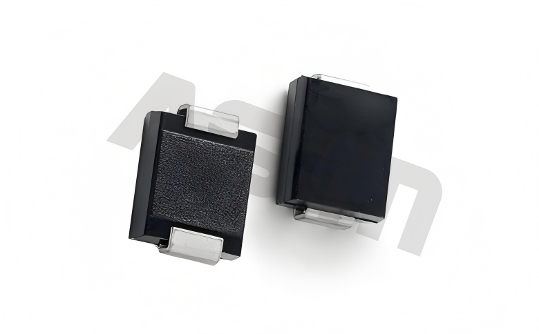
12V power bus (load dump) | SM8S 26V | 26V, 6600W, VC=42V, SM8S | Grade 1 ✓ |
24V power bus | SM8S 33V | 33V, 6600W, VC=53V, SM8S | Grade 1 ✓ |
6. About ASIM
ASIM (Shenzhen ASIM Electronics Co., Ltd.) was founded in 2013 and is headquartered in Shenzhen, China. The company specializes in the design and development of ESD protection diodes and TVS transient voltage suppressors, with ESD representing approximately 42% of revenue and TVS approximately 25%.
ASIM holds status as a National High-Tech Enterprise and Shenzhen Specialized Innovation Enterprise, with 30+ issued patents. The company operates a 20M RMB in-house EMC laboratory (2024) equipped with TESEQ NSG-437 ESD simulators, PRIMA surge generators, 3CTESET load dump generators, and full FA capability (X-RAY, SEM, cross-section analysis). ASIM provides on-site support within 4 hours for customers in Guangdong Province.
ASIM products have been validated in mass-production programs for OPPO, HUAWEI, ASUS, Haier, Changan, Hongqi (FAW), Geely, GAC, Toyota, Ubtech, and others. Previous

Related News

2024.10.12
EMC testing Contents and Current Situation of Automotive Electronic products

2025.02.21
How to choose the best circuit protection devices in a circuit?
2025.08.25
TVS diodes solve the problem of WIFI disconnection in routers due to ESD interference-ASIM

2025.09.01
Characteristics of Unidirectional ESD diodes -ASIM
2025.09.05
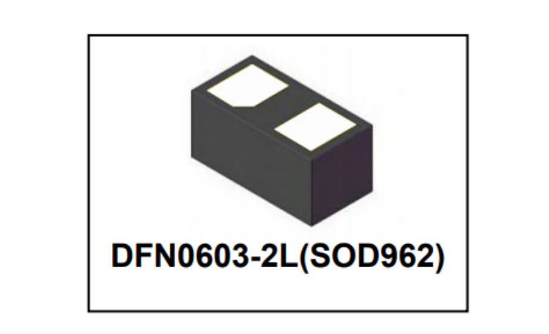
ESD5E001TA Bidirectional TVS Diode Technical Specification -ASIM
2025.09.09
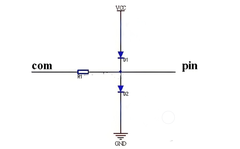
Analysis of Misunderstandings in TVS Tube Clamping Voltage Selection and Calculation -ASIM
2025.09.10
The Function and Working Principle of MOSFETs -ASIM
2025.09.12
How to effectively dissipate heat and solve the problem of severe heating of MOSFETs? - Shenzhen ASIM
2026.05.19
What Is an ESD Diode? Working Principle, Key Parameters & Selection Guide
2026.06.10
ESD protection for the gate of SiC/GaN power devices: Why it is more difficult to protect than IGBT


