Submit






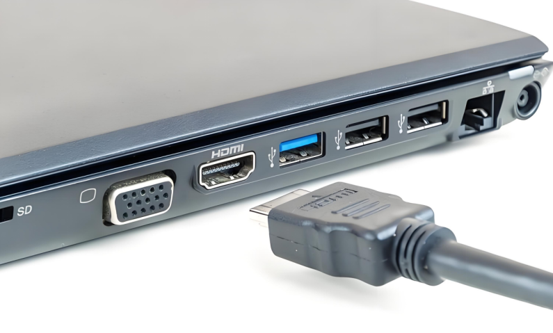
An industrial IoT gateway often places a 24 V supply, long RS-485 cable, Ethernet magnetics, and a USB service port on one assembly. Each port requires its own protection window.
Short answer: Use the measured maximum continuous voltage and surge environment for the 24 V input, the transceiver common-mode window and bus topology for RS-485, and the magnetics/PHY placement plus bandwidth for Ethernet. Do not reuse a power TVS on a data pair without a separate evaluation.
Build a requirement table for each exposed interface
| Interface | Normal condition | Primary selection constraint | Board-level check |
|---|---|---|---|
| 24 V DC input | Supply tolerance and cable transients | VRWM, VC, IPP, power | Start-up, surge, temperature |
| RS-485 A/B | Differential signaling and common mode | Voltage window, capacitance, symmetry | BER and reconnect |
| Ethernet | High-speed link through magnetics | Protection location and common-mode path | Packet loss and emissions |
| USB service port | 5 V power and data | VRWM, low capacitance, layout | Enumeration and transfer |
A useful failure record includes reboots, packet loss, CRC errors, port reconnect time, clock synchronization, and post-test thermal behavior—not only whether the gateway stayed on.
Four boundaries to verify before approving a device
1. Working voltage
Use the measured maximum continuous input, not the nominal 24 V label. On data lines, verify both differential and common-mode operation so the protection does not conduct during a valid signal.
2. Capacitance and signal bandwidth
Ethernet and USB require tight control of parasitic loading. RS-485 may tolerate more capacitance at lower data rates, but cable length, node count, and the actual bit rate still need board testing.
3. Clamping data and its test condition
For the power input, compare VC at the intended pulse current with the downstream converter rating. For RS-485, include the transceiver pin tolerance and series impedance in the evaluation.
4. Package, placement, and return path
Keep the power protection loop compact, place balanced RS-485 protection close to the connector, and define the Ethernet return path around the connector and magnetics instead of treating ground as an ideal node.
A repeatable board-validation sequence
Record supply tolerance, cable length, grounding, RS-485 bit rate, and Ethernet speed.
Test power, communication, and enclosure paths separately.
Capture input voltage, reset, packet loss, CRC counters, and system logs.
Keep termination, software load, and cable placement fixed for A/B comparisons.
Repeat communication margin, start-up, temperature, and long-duration transfer tests.
How ASIM public data can support candidate screening
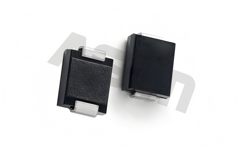
The public ESD24R300TA datasheet lists ±24 V VRWM, a 26.5–30 V breakdown range at 1 mA, and 8/20 μs clamping points of 36 V at 1 A and 48 V at 8 A. These values support a candidate comparison, but the gateway input tolerance, downstream rating, expected pulse current, and thermal design determine suitability.
Traceable numbers make a comparison auditable. They do not replace testing on the target assembly, and a component ESD rating must not be presented as the immunity level of the finished product. IEC 61000-4-2 defines the system-level test method; the applicable product standard and test plan determine levels and performance criteria.
Questions engineers often ask
Can a 24 V bus automatically use a 24 V VRWM TVS?
No. Measure maximum continuous voltage and tolerance, then compare breakdown, clamping, and downstream limits.
Can RS-485 and Ethernet share the same TVS?
Do not assume so. Their signal range, common mode, bandwidth, topology, and capacitance budgets differ.
Is “no reboot” a sufficient immunity criterion?
No. Include packet loss, CRC errors, reconnect behavior, data integrity, and post-test operation.
 Previous