Submit






A higher TVS peak pulse power rating does not automatically mean better protection. Peak pulse power belongs to a defined waveform, pulse width, current, starting temperature, and mounting condition. TVS selection begins with the highest continuous voltage and downstream voltage limit, then compares clamp performance and thermal stress under the same surge condition.
Stop ranking 400 W, 600 W, and 1500 W as isolated numbers
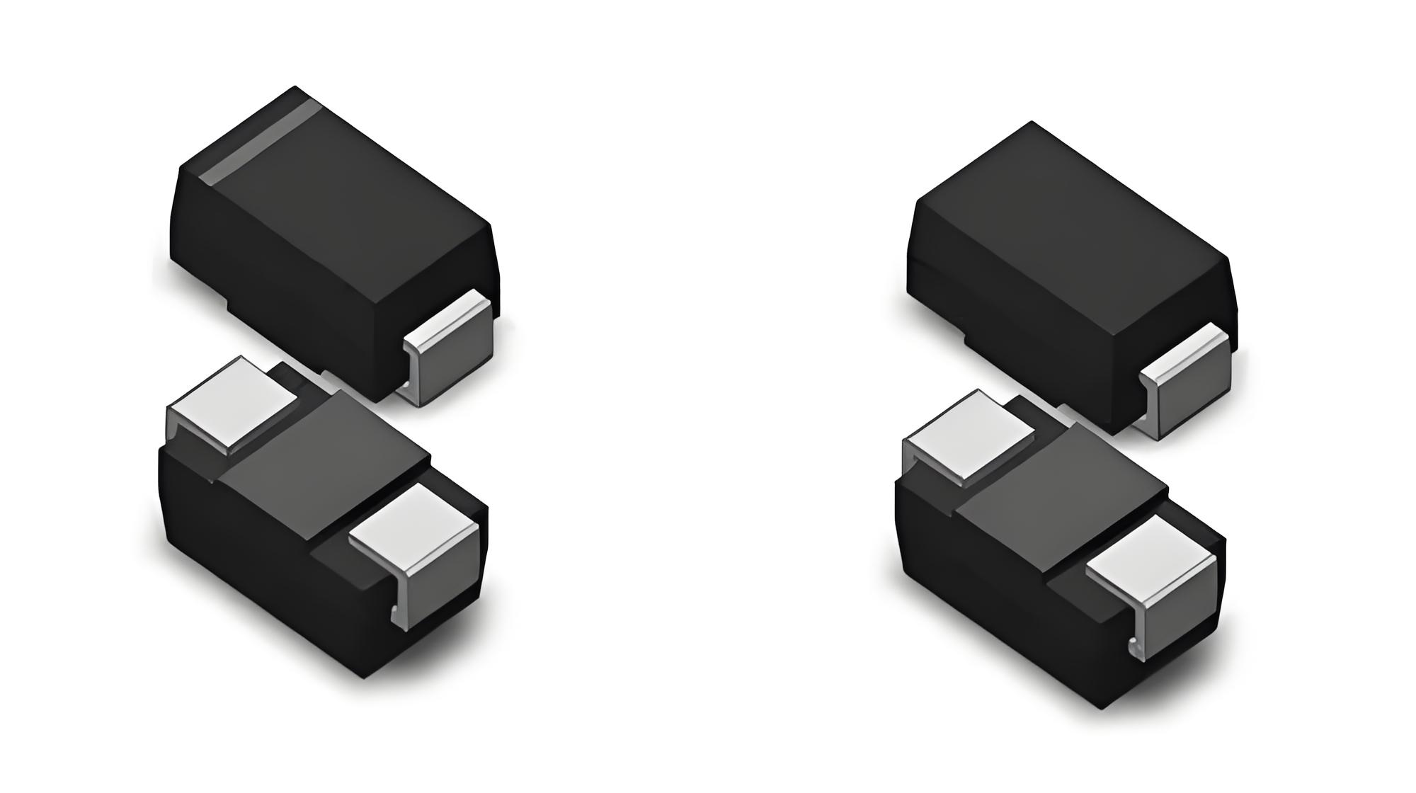
Catalog power commonly refers to a specified transient waveform and laboratory condition. Larger SMA, SMB, or SMC packages can accommodate different die and thermal structures, but a package name does not fix one power class. Product series and manufacturers can define ratings differently, so wattage labels alone do not create an alternate-source table.
Collect these conditions before comparing power:
surge waveform, pulse width, source impedance, and repetition;
TVS VRWM, breakdown range, VC, and the corresponding IPP;
starting junction or ambient temperature and derating information;
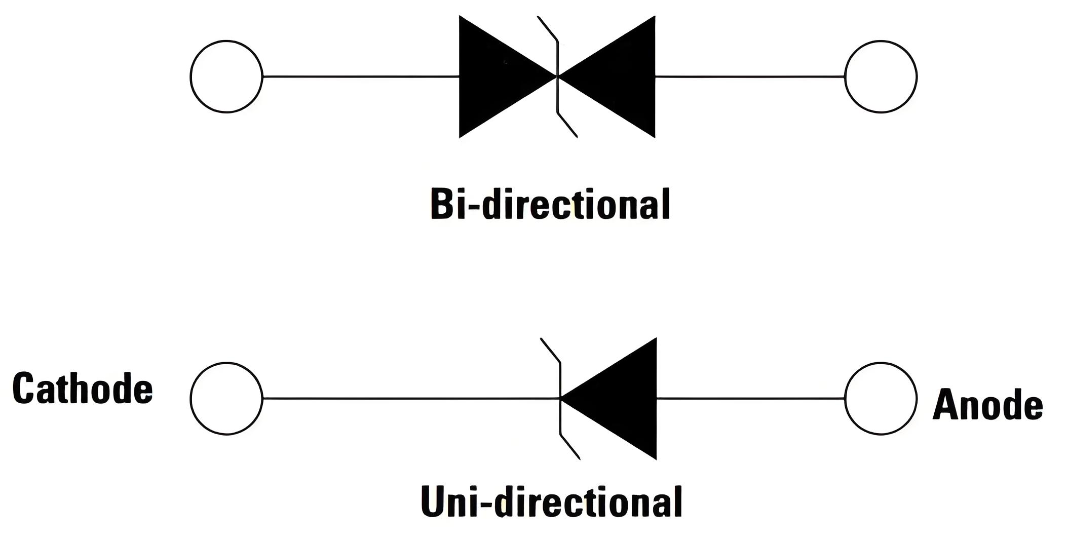
unidirectional or bidirectional construction;
package thermal path, land pattern, copper area, and nearby heat sources;
maximum voltage of the downstream converter, MOSFET, capacitor, and monitor;
continuous high-line and sustained fault behavior.
If two VC values use different pulse currents, they cannot show which part protects the node better. The same discipline applies to peak power.
Use a TVS for a defined transient, not sustained overvoltage
A TVS can absorb or divert a specified short-duration event. When the input remains above its working boundary, the device may conduct continuously and overheat. A large peak pulse rating does not replace an eFuse, hot-swap controller, crowbar, fuse, or supply shutdown for sustained overvoltage.
Follow this design sequence:
Measure the highest continuous port voltage over tolerance and temperature.
Define the project surge waveform, source impedance, and repetition.
Estimate the current that reaches the TVS after upstream impedance.
Read maximum VC at the comparable current and waveform.
Add overshoot from package, trace, via, and return inductance.
Compare the protected-node voltage with every downstream absolute maximum.
Check pulse energy, cooling interval, board temperature, and copper area.
Recheck leakage and function after stress.
This order prevents a part from passing the peak-power screen while failing normal high-line operation or residual-voltage margin.
Read VC and IPP together to estimate the actual peak
For the same specified point, VC multiplied by IPP gives an approximate peak pulse power check. It is still a pulse peak, not continuous dissipation. Dynamic resistance and PCB inductance can raise the sensitive-node voltage above the TVS terminal value. A larger package may improve pulse capability without reducing the clamp window enough for a low-voltage downstream device.
ASIM TVS products cover different working-voltage and package classes. Exact part numbers can support examples inside an engineering article, but the stronger website topic explains how waveform, current, clamp voltage, and downstream tolerance fit together. Repeating a catalog page around one model does not answer the system question.
Probe the TVS terminals and the sensitive input node during a representative bench pulse when safe measurement is available. The difference between the two traces reveals path overshoot. Improve the return route before assuming that another power class will solve the voltage.
Calculate energy for long and repetitive pulses
Load dump, long surge events, or rapid pulse trains can contain much more energy than a short impulse. A lower peak current can still produce greater junction heating when the pulse lasts longer. Short-pulse PPPM should not be copied into a long-pulse design without applicable transient-thermal data.
Board implementation changes the thermal boundary. Small pads, plane slots, high ambient temperature, and a nearby converter can reduce the available margin. One cold-start pulse on an open bench does not represent a product operating at maximum load inside an enclosure.
When transient thermal information is incomplete, request the applicable data from the manufacturer and test on a representative PCB. Record the starting temperature, interval, pulse count, and post-stress leakage. A passing functional check can miss early device degradation.
Questions that expose a weak TVS comparison
Does a 1500 W TVS always clamp lower than a 600 W TVS?
No. Clamp voltage depends on working voltage, breakdown range, dynamic resistance, and pulse current. Compare maximum VC at comparable conditions rather than infer clamp quality from power.
Can peak pulse power be used as continuous power?
No. PPPM describes a defined short event. Sustained overvoltage needs current limiting, shutdown, or another protection architecture.
Do all TVS devices in an SMA package share the same power rating?
No. Package category does not fix die, series rating, waveform, temperature, or manufacturer definition. Review the exact approved data.
The final selection report should answer three separate questions: the TVS does not conduct during valid operation, the residual voltage remains within downstream limits at the target surge current, and the thermal stress is acceptable for the defined pulse and repetition. A statement that peak power is sufficient does not close the design.
For production release, tie the approved TVS class to one input architecture and one board revision. Record adapter tolerance, cable length, upstream resistance, fuse or eFuse behavior, copper area, enclosure temperature, and the exact surge generator configuration. Repeat the critical pulse on more than one assembled board and include high-line operation before the pulse. This catches a design that survives from a cold start but enters unwanted conduction after the enclosure reaches operating temperature.
Alternate-source approval needs the same discipline. A replacement with a larger wattage label may have a wider breakdown spread or higher clamp voltage. Compare maximum values under aligned conditions, build the candidate on the same PCB, and inspect leakage after stress. Purchasing approval should refer to the engineering boundary instead of treating package and wattage as sufficient equivalence.
 Previous