





 Submit


What are the three key elements of the EMC issue?
 2024.12.06 00:00:00
 544
544





In other words, the three elements that cause electromagnetic compatibility problems are: the electromagnetic interference source, the coupling path, and the sensitive equipment. Radiated interference contaminates the spatial electromagnetic environment in the form of electromagnetic waves through the enclosure and connection lines; conducted interference is caused by interfering with the public power grid through power lines or by affecting the connected equipment through other terminals (such as radio frequency terminals, input terminals).
Conduction, radiation, interference sources - (pathways) - near-field coupling of sensitive receptors with possible interference sources of AV devices
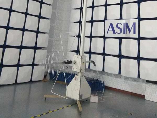
(a) Frequency modulation receiver, local oscillator of TV receiver, fundamental and harmonic waves generated by high-frequency head, local oscillator circuit;
(b) Switching pulses of the switching power supply and high-order harmonics, synchronization signal, square waves and high-frequency harmonics of line field signal, high-frequency harmonics generated by line scanning imaging circuit;
(c) Various clock signals and high-frequency harmonics required by digital circuits, as well as their combinations, such as CPU chip working clock, MPEG decoder working clock, video synchronization clock (27 MHz, 16.9344 MHz, 40.5 MHz), etc.;
(d) Digital signal square waves and high-frequency harmonics, high-order harmonics generated by crystal oscillator, useless signals and stray signals caused by nonlinear circuit phenomena (nonlinear distortion, intermodulation, saturation distortion, cutoff distortion);
(e) Non-sinusoidal waves, waveform spikes, overshoot, ringing, parasitic frequency points in circuit design.
(f) For sensitive sensors, external interference includes surges, fast pulse strings, static electricity, voltage drop, voltage changes and various electromagnetic fields.
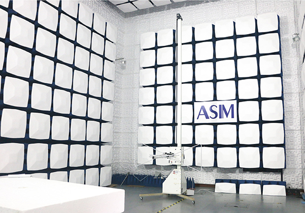
Electromagnetic interference characteristics
① The spectrum of a single pulse is the widest;
② The low-frequency content of the spectrum depends on the area of the pulse, and the high-frequency components depend on the sharp edges of the steep pulse;
③ The horizontal level of the crystal oscillation must reach a certain range, so digital circuits can operate in a specific time sequence. Therefore, the characteristics of the interference generated by the crystal oscillator include bandwidth and high interference levels;
④ When the antenna polarization directions are the same, EMI radiation and reception are the most severe;
⑤ Interference methods: radiation, conduction, coupling, and radiation, conduction, and coupling.
⑥ The main disturbance of power lines is caused by common-mode current;
⑦ The radiation interference generated by the loop is mainly caused by differential-mode current.
Understanding the three major laws of electromagnetic compatibility and the three major elements of electromagnetic compatibility problems will make electromagnetic compatibility problems a normal situation. Following the laws of EMC can save time and effort in solving EMC problems and achieve twice the result with half the effort.
EMC design, in a nutshell, is to carefully predict all possible EMC problems, optimize the selection of schemes and circuits, find a design scheme to optimize the circuit, mechanical structure and PCB, improve the design quality of the product, and ensure that it meets functional and performance indicators, considering cost-effectiveness, and avoiding electromagnetic compatibility problems. To suppress and eliminate interference sources, reduce the frequency of high-frequency signals, reduce the area of high-frequency current loops, reduce common impedance coupling or inductance coupling, common measures include low-speed low-radiation devices, shielding boxes, shielding cables and I/O filters.
 Previous

Related News

2025.02.21
How to choose the best circuit protection devices in a circuit?
2026.07.28
How to Rectify EMC Conducted Emission Failures? Troubleshooting Methods Ranging from Frequency Point Identification to Power Supply Filtering
2026.08.04
How to implement ESD remediation for devices with plastic housings? Design considerations for buttons, cutouts, and internal PCB dimensions.

2026.08.05
How to Read TVS Diode Reverse Leakage Current (IR): Temperature, VRWM, and Standby Power
2026.08.05
How to Read TVS Diode Peak Pulse Power: Waveform, Temperature, and Pulse Width A 200 W, 600 W, or 1500 W rating on a TVS diode is peak pulse power under a defined waveform and starting temperature. It is not continuous power dissipation. PPPM must be read together with pulse width, waveform, peak pulse current, clamping voltage, and thermal derating. The same TVS can tolerate very different peak currents for a short, fast pulse and a longer surge. Unless the test conditions match, a 1500 W dev
2026.08.07
How to Estimate TVS Diode Dynamic Resistance From VC and IPP


