Submit






A surge voltage value does not define the stress on a TVS diode by itself. The source impedance and waveform determine how much current can flow after the device starts clamping. Two generators can both be described as 1 kV sources and yet deliver very different peak current, pulse energy, and residual voltage. TVS selection must pair voltage with source conditions.
The missing number behind a surge voltage
Suppose an unprotected line rises toward an open-circuit surge voltage, and a TVS begins to hold the protected node near its clamping voltage. A first-order circuit view gives a useful relationship:
TVS current is approximately (source voltage − clamping voltage) / source impedance.
This is not a replacement for the full generator waveform or circuit simulation. It shows why the source cannot be ignored. If the effective impedance is high, only a limited current reaches the suppressor. If it is low, a small change in clamping voltage can correspond to a large change in current. The source cable, coupling network, series resistance, transformer, supply output impedance, and installation wiring all contribute to the real event.
Datasheets describe a device under stated test conditions. A peak pulse power number is linked to a waveform, pulse duration, starting temperature, and repetition assumptions. It should not be divided by an arbitrary voltage and applied to every transient source.
Open-circuit voltage and short-circuit current tell different stories
A surge generator may be characterized by the voltage it produces without a load and the current it produces into a short circuit. These quantities are related through the generator network, but the TVS operates between those two extremes. Its dynamic voltage-current behavior changes the current, and the current changes its clamping voltage.
For engineering review, keep the following values together:
open-circuit voltage and short-circuit current when defined by the source;
source or coupling impedance and the relevant waveform;
line operating voltage, tolerance, ripple, and abnormal continuous conditions;
TVS reverse working voltage, breakdown range, test current, and clamping point;
downstream absolute maximum voltage and any series impedance between the TVS and load;
pulse repetition, ambient or case temperature, and expected lifetime exposure.
Removing any one of these can lead to a plausible but wrong comparison. A TVS with a lower published clamping number may have been measured at a lower current. A higher-power package may still be unsuitable if its working voltage allows excessive residual voltage at the protected IC.
Match the operating window before calculating pulse stress
The TVS must remain appropriately off during every valid operating state. Nominal voltage alone is not enough. Charging systems, automotive rails, industrial supplies, and long cables can spend meaningful time above nominal because of regulation tolerance, charging profiles, or planned operating modes. Selecting a reverse working voltage too close to the top of that window can increase leakage or unintentionally load the line.
The opposite error is choosing a very high working voltage to avoid leakage without checking the protected circuit. Breakdown and clamping then move upward, potentially exposing the load to a voltage beyond its tolerance. The useful device sits between the maximum continuous line condition and the maximum transient the downstream circuit can safely withstand.
Sustained overvoltage requires its own protection. A TVS designed for transient absorption should not be expected to dissipate a wrongly connected adapter or a long regulator fault indefinitely. Fuses, electronic disconnects, current limiting, crowbar functions, or wider system changes may be required.
Use the source waveform that belongs to the application
Not every transient called a “surge” has the same rise time and duration. Compliance generators, inductive load switching, cable discharge, automotive pulses, and hot-plug ringing represent different sources. A part tested with one standardized pulse does not automatically have the same capability under a longer or repetitive event.
The selection process should follow a defined route:
Identify the external event and the applicable standard or measured field waveform.
Record the source voltage, source impedance, pulse shape, repetition, polarity, and coupling path.
Define the line's maximum continuous operating window and the downstream voltage limit.
Select candidate TVS devices whose working and breakdown regions fit that window.
Evaluate current, clamping voltage, pulse energy, temperature, and package capability under comparable conditions.
Include PCB trace inductance and any intentional series impedance in the model.
Measure voltage at the protected load on the real board as well as across the TVS terminals.
Inspect the device and system after repeated pulses for leakage, drift, functional errors, and thermal damage.
This method produces a traceable decision even when the final answer requires bench testing. It also makes it clear which assumptions must be revisited if the cable, power architecture, standard, or installation changes.
PCB inductance creates voltage the datasheet cannot include
During a fast current rise, the connection from the surge entry to the TVS and from the TVS to the return path adds inductive voltage. A long branch can let the transient continue toward the load before current is diverted. The voltage measured at the IC can therefore exceed the voltage measured directly across the suppressor.
Place the TVS at the entry boundary, route the incoming trace through or immediately past its pads, and provide a short, wide return to the intended reference or chassis path. Keep the protected side physically separated from the dirty entry side. If both sides run in parallel, electric and magnetic coupling can bypass the component.
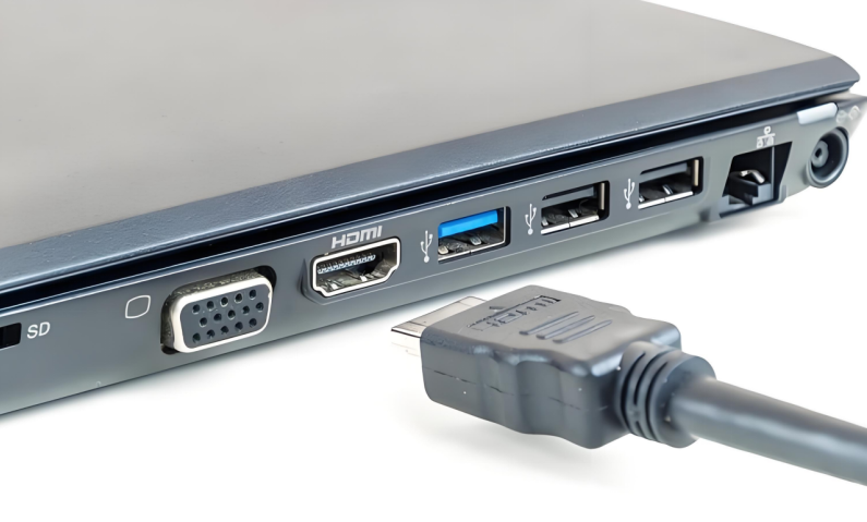
For a connector that combines power and high-speed data, do not force one device type onto every pin. The power path may need higher pulse capability, while data lines need low capacitance and a voltage window matched to their signaling. Each path also needs its own return geometry.
A worked comparison without pretending the source is universal
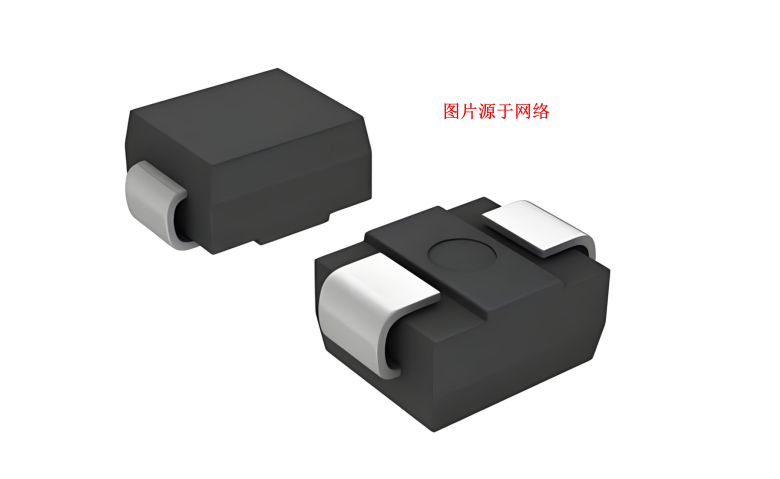
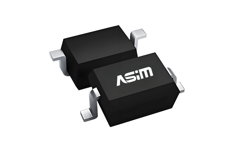
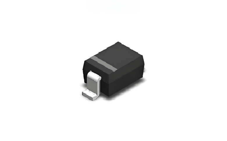
ASIM SMA04J24V is a unidirectional TVS in an SMA/DO-214AC package. Its published parameters include a 24 V reverse working voltage, a 26.7–29.5 V breakdown range, 10.3 A peak pulse current, and 38.9 V maximum clamping voltage under the stated condition, with a 400 W peak pulse power rating tied to the specified waveform.
Those figures can support a candidate review for a line whose valid continuous voltage fits below 24 V and whose expected pulse resembles the datasheet conditions. They do not prove suitability from the phrase “24 V system.” The engineer still has to check maximum charging or regulation voltage, source impedance, waveform, repetition, downstream tolerance, polarity, thermal environment, and layout.
If the actual source can only provide a much smaller current, the operating point may be below the published peak clamping condition. If the source is lower impedance or the pulse lasts longer, the device may face greater stress than the headline power number suggests. Testing at the protected node closes this gap.
Record enough context for the next engineer
A useful TVS selection note contains the source model, circuit operating limits, candidate datasheet revision, compared test points, layout image, oscilloscope locations, pulse count, temperature, and post-stress leakage. Writing only “passed 1 kV” discards the information needed to reproduce or reuse the design.
Source impedance is therefore not an academic detail. It connects the generator voltage to the current the suppressor must conduct and the clamping voltage the protected circuit will actually see.
TVS Source Impedance FAQ
Can two 1 kV surge sources produce different TVS current?
Yes. Their source impedance, waveform, coupling network, and wiring can produce different current, energy, and clamping conditions even with the same open-circuit voltage.
Can I calculate TVS current by dividing 1 kV by the TVS resistance?
No. A TVS is nonlinear, and the generator plus circuit determine the operating point. Use the specified source network, device curves or test points, and board measurements.
Where should clamping voltage be measured?
Measure at the protected load as well as near the TVS. PCB and return-path inductance can create additional residual voltage between the suppressor and the IC.
Copyright notice:Copyright belongs to Shenzhen ASIM Electronics Co., Ltd. Please retain the author, source, and original URL when quoting or republishing.
Original URL: https://asim.com.cn/source-impedance-tvs-diode-selection-en.html
 Previous