





 Submit


SMA04J24V: 400W 24V TVS Selection and Input Layout
 2026.08.21 00:00:00
 51
51





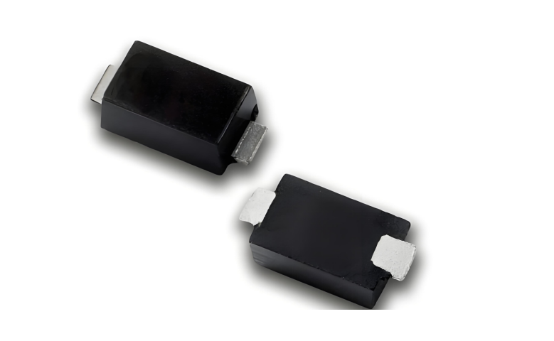
SMA04J24V is an ASIM unidirectional TVS diode in the SMA/DO-214AC package. Its verified values are 400 W peak pulse power, 24 V reverse working voltage, 26.7 V to 29.5 V breakdown range, 10.3 A peak pulse current, 38.9 V maximum clamp voltage, and 1 microampere reverse leakage. The 24 V name does not mean the part automatically fits every 24 V supply. The highest continuous input and downstream voltage limits must be measured first.
Measure the highest continuous input at the board
Industrial adapters, battery systems, and regulated supplies can exceed their nominal label during light load, charging, adjustment tolerance, or operating transitions. Reverse working voltage is screened against the highest continuous value at the TVS location, not against the product name on the supply.
Build an input envelope that includes:
stable voltage at rated load, light load, and no load;
startup, shutdown, hot-plug, and recovery states;
supply tolerance and cable drop;
temperature conditions that affect leakage;
measurement location relative to the connector, fuse, and reverse-polarity element.
If normal operation approaches 24 V closely, available leakage margin becomes small. A single room-temperature measurement cannot represent the complete condition.
Use the breakdown range as a transition window
SMA04J24V has a breakdown range from 26.7 V to 29.5 V. Breakdown voltage is not the same as the protected voltage during the surge. It marks a defined device conduction region under a specified test condition. The actual transient operating point moves toward the clamp value as current increases.
Review the input voltage stages in order:
Use the maximum continuous input to screen the 24 V working voltage.
Review the 26.7 V to 29.5 V breakdown range for available operating margin.
Use the 38.9 V clamp together with the 10.3 A condition.
Add PCB and interconnect overshoot.
Compare the result with every downstream component limit.
Do not use breakdown voltage as a substitute for clamp voltage. They answer different questions.
Compare 38.9 V with the complete downstream chain
The 38.9 V maximum clamp is measured at the TVS terminals under the stated current condition. The converter input pin can see additional overshoot caused by trace and via inductance between the TVS, return, input capacitor, and protected stage. Measure at the downstream pin when the test setup and probe bandwidth allow it.
List the voltage limits of the reverse-polarity MOSFET, input capacitor, DC/DC converter, supervisor, and any sensing network. The lowest limit can define the available margin. A TVS that remains electrically healthy after the event does not prove that the downstream chain stayed inside its ratings.
Use a short measurement return. A long probe ground lead can create a loop and display overshoot that belongs to the measurement connection rather than the board.
Understand what the 400 W rating does and does not say
The 400 W figure is a peak pulse rating under its specified waveform, pulse duration, temperature, and mounting assumptions. It is not a continuous dissipation rating. It also cannot be compared blindly with another family's number measured under a different condition.
For longer surges, the energy integral, repetition interval, temperature, and heat flow into the package and PCB become important. A higher headline peak power does not fix a reverse working voltage mismatch or an excessive downstream clamp.
The unidirectional configuration also matters. In the opposite polarity, the device behaves through its forward conduction path. Continuous reverse connection needs current limiting or disconnect protection; it should not rely on the TVS absorbing indefinite energy.
Draw the connector-to-return surge loop
Place the TVS close to the input connector and give it a wide, direct return to the input negative reference. The preferred current loop runs from the connector through the TVS and back to the connector return without crossing deep into the digital ground region. A TVS located near the converter but far from the connector can leave a long inductive segment exposed.
Show the connector, fuse, reverse-polarity device, TVS, filter, input capacitor, and converter on one placement view. Mark the order and return path. Avoid sharing the high-current transient return with reset, current-sense, or low-level analog routes.
Copper area helps thermal spreading, but it should not lengthen the surge loop. Balance thermal and transient requirements in the final layout.
Validate normal operation after every stress change
Capture connector-side and downstream waveforms when practical. Then check startup, load steps, standby current, and TVS temperature. Measure leakage or input current again after repeated stress, because an increase can reveal damage even when the device is not shorted.
Use an A/B/A sequence when moving the TVS or changing the input network. Keep the supply, cable, load, board, and firmware fixed. A single successful event cannot establish a production result.
Inspect the input network again after the test for leakage, discoloration, cracked solder, or a changed startup current. These checks can reveal degradation that a simple continuity test misses.
The release record should contain:
the measured continuous input envelope;
SMA04J24V parameters and their stated conditions;
a placement image of the complete input chain;
downstream limits and measured stress behavior;
startup, thermal, leakage, and repeated-stress results.
Questions about SMA04J24V application
Does a nominal 24 V supply automatically fit a 24 V TVS?
No. Measure the highest continuous board voltage and include tolerance, operating transitions, temperature, and leakage margin.
Can 400 W be compared without the pulse waveform?
No. Peak power depends on waveform, pulse duration, temperature, and mounting. Compare like-for-like conditions.
Is the downstream circuit safe when the TVS stays below 38.9 V?
Not automatically. The receiver can see PCB overshoot, and every device in the input chain has its own voltage limit.
 Previous

Related News
2025.09.03
What are the advantages of bidirectional TVS diodes? How to distinguish the polarity of TVS Diodes -ASIM
2026.06.11
ESD Protection for High-Speed Automotive Interfaces
2026.06.22
TVS Diode VRWM, VBR, and VC: Parameter Relationship Guide
2026.07.20
How should a failure in the CAN communication surge test be handled?

2026.08.05
How to Read IEC 61000-4-2 Ratings for ESD Diodes: Component Rating vs System Compliance
2026.08.07
How to Estimate TVS Diode Dynamic Resistance From VC and IPP


