





 Submit


How to Read IEC 61000-4-2 Ratings for ESD Diodes: Component Rating vs System Compliance
 2026.08.05 00:00:00
 88
88





An IEC 61000-4-2 rating on an ESD diode describes the component's performance under a defined test connection, polarity, and failure criterion. It does not prove that a finished product will pass at the same voltage. System behavior also depends on the discharge point, enclosure, connector, clamp voltage, PCB layout, and high-frequency return path.
When a datasheet states a contact or air-discharge voltage, first determine whether the number is a component test or a system requirement. Then check the current waveform, number of strikes, polarity, and pass/fail definition. Copying the voltage into a BOM is not a complete ESD design.
Why is a component rating different from a system rating?
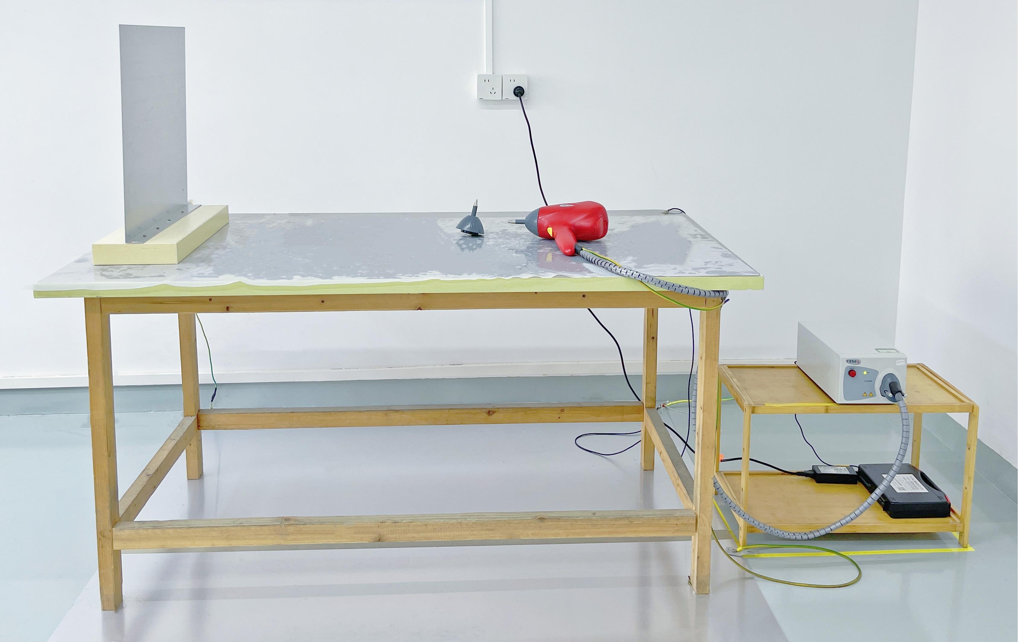
A component test applies the pulse to defined pins with a specified fixture. The result may be based on physical damage, leakage shift, or another component-level criterion. In a system test, the discharge is applied to a user-accessible point. Current can travel through the connector shell, enclosure seam, cable shield, signal trace, ground plane, or free-space coupling before it reaches the protection device.
The same ESD diode can produce different results on two PCBs. One board places the device beside the connector and returns current through a short, low-inductance path. The other uses a long branch to a distant digital ground. The second board adds inductive voltage to the device's clamp voltage and exposes more of the PCB to the pulse.
System criteria are also broader than component survival. A product can reset, lose communication, corrupt data, or lock up while the ESD diode remains physically intact. Whether automatic recovery is acceptable must be defined before testing.
What should be checked besides the IEC voltage?
Working voltage and leakage
VRWM must cover the normal voltage range of the protected line. A lower-voltage ESD diode may provide a tighter clamp, but it can leak or conduct during normal operation if the signal approaches its working voltage. High-speed interfaces also require a capacitance check.
Clamping voltage at a stated current
VBR marks the beginning of avalanche breakdown. VC is the maximum clamping voltage at a specified pulse current. Two devices with the same advertised IEC level can have different VC values and dynamic resistance. The protected IC sees the device voltage plus the overshoot created by PCB parasitic inductance.
The ASIM ESD5D002SA is a bidirectional low-capacitance device with a 5.0 V VRWM, a minimum VBR of 6.0 V, and a typical junction capacitance of 0.2 pF. Its maximum VC is 12.0 V at 8.0 A, and it uses a DFN1006-2L package.
Those parameters help evaluate voltage margin, signal loading, and clamping. They do not, by themselves, establish the ESD level of a complete product. The component withstand condition must still be checked in the full part data, while the product must be verified in its actual enclosure and operating state.
How does PCB layout change the result?
Place the ESD diode close to the point where the pulse enters. The path from connector to protection device must be short, and the path from the device to the high-frequency return must also be short. Optimizing only one side leaves significant inductance in the other.
Route the protected line through the protection node before it continues to the IC. Avoid a long main trace with a side branch to the TVS diode. On differential pairs, keep the two device pads, vias, and trace transitions as symmetrical as possible.
Chassis ground, shield ground, and digital ground need a deliberate high-frequency relationship. A metal enclosure often benefits from a short, continuous chassis return. A plastic enclosure requires more attention to arc-through paths and field coupling through seams, buttons, and display windows.
A wire can read as a short circuit on a multimeter and still be a poor ESD return. The fast edge of the discharge makes even a short length of narrow conductor inductive.
Why can a higher-rated diode fail to fix the product?
The disturbance may not be entering through the line where the diode was replaced. It can arrive through VBUS, a cable shield, power ground, a button opening, or direct field coupling into reset and clock circuits. Record the discharge point, polarity, failure symptom, and reset cause before changing parts.
Placement can also defeat the component. If the diode is far from the connector, the pulse has already travelled across the board before it is clamped. A long ground connection then adds more residual voltage. Raising the component's advertised withstand level may produce little improvement.
ASIM evaluates ESD candidates by linking VRWM, VC, pulse current, capacitance, package, and system current path. The component rating narrows the candidate list; the board and enclosure test determine whether the design passes.
How should an ESD test failure be investigated?
Monitor the main power rail, reset pin, clock, interface state, and fault logs during the discharge. Separate external reset, brownout, watchdog, software exception, and transceiver failure. A generic note such as "the unit rebooted" does not identify the coupling path.
Change one variable at a time. Shorten the return path, move the protection device, or test a lower-VC candidate, then restore the original condition. If the failure follows the change in an A/B/A sequence, the evidence is much stronger than a single passing run.
Common questions about ESD diode ratings
Does a ±15 kV air-discharge rating guarantee a ±15 kV system result?
No. The component fixture and the product discharge path are different. Air discharge also depends on approach, environment, geometry, and the actual arc point.
Is component HBM the same as IEC 61000-4-2?
No. HBM is commonly used for component handling sensitivity. IEC 61000-4-2 is a system-level immunity method with a different discharge network and energy condition.
Is the device with the lowest VC always the best choice?
Not automatically. VC must be compared at the stated current, and the device still needs adequate VRWM, acceptable leakage, suitable capacitance, and the correct polarity configuration.
If the product recovers automatically, has it passed?
That depends on the required performance criterion. Some products allow a brief degradation followed by automatic recovery. Others cannot tolerate a communication interruption or loss of a safety function.
A release review should include the component withstand condition, VRWM, VC at the relevant current, capacitance, physical placement, return path, and system performance criterion. A high voltage rating without those details is only a partial selection.
 Previous

Related News

2024.10.12
EMC testing Contents and Current Situation of Automotive Electronic products

2025.02.21
How to choose the best circuit protection devices in a circuit?
2026.07.13
How do I select a 5V low-capacitance ESD diode model?
2026.07.13
What should be done if a USB interface fails ESD testing?
2026.07.22
What is the difference between ESD arrays and single-channel ESD devices? A selection guide for multi-channel interfaces.

2026.07.24
What are the differences between SMA, SMB, and SMC packaged TVS diodes? Selection based on power and size.
2026.07.25
What are the differences between load dump, surge, and ESD? Strategies for automotive power supply transient protection.
2026.07.29
Why does the ESD test still fail after replacing the protection device? Troubleshooting discharge paths, grounding, and component placement.
2026.08.04
How to handle an MCU reset pin susceptible to ESD interference? Checking RC circuits, supervisory chips, and PCB traces.

2026.08.05
How to Read TVS Diode Reverse Leakage Current (IR): Temperature, VRWM, and Standby Power


