Submit






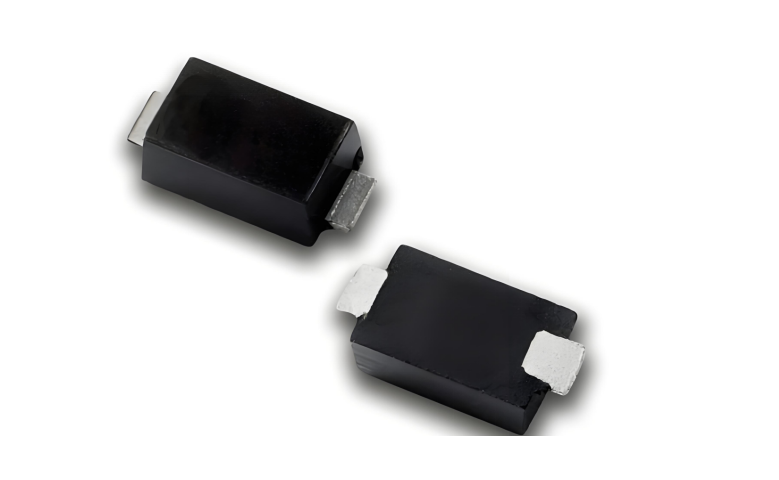
TVS diodes are used at circuit boundaries where a transient overvoltage can enter a product. Common locations include DC power inputs, long industrial communication lines, and user-accessible connectors. The device remains in a high-impedance state during normal operation and conducts during a transient, diverting current into a defined return path while limiting the voltage at the protected node.
Direct answer: use the application to set the review order. A power input starts with maximum continuous voltage, surge waveform, and downstream absolute maximum voltage. An industrial bus adds common-mode range, fault voltage, and cable coupling. A high-speed connector moves capacitance, package parasitics, and signal integrity much earlier in the decision.
Three application groups require three different checklists
| Application | Typical exposure | First data-sheet checks | Board-level evidence |
|---|---|---|---|
| DC input or adapter port | Switching overshoot, inductive interruption, surge | Maximum bus voltage, VRWM, VBR, VC, IPP, pulse waveform, thermal derating | TVS current, voltage at the protected node, temperature rise, post-stress leakage |
| RS-485, CAN, or another cabled bus | ESD, EFT, surge, ground offset, continuous fault voltage | Bus common-mode range, polarity, VRWM, leakage, capacitance, clamp point | Communication waveform, error rate, current return path, stress recovery |
| USB, HDMI, control, or user-accessible I/O | Human-body ESD and connector transients | VRWM, capacitance with test conditions, dynamic clamp behavior, channel configuration | Eye diagram or functional baseline, ESD result, post-stress leakage |
This table does not set a compliance level. The applicable product standard and the approved test plan define generator settings, coupling networks, operating modes, and performance criteria. A component rating is an input to the design; it is not a system pass result.
Power-input protection starts with the real operating window
A nominal 24 V rail is not automatically a 24 V maximum rail. Supply tolerance, ripple, charging behavior, adapter variation, and allowed abnormal states can all raise the voltage that appears continuously. The TVS reverse working voltage, VRWM, must be reviewed against that upper limit. Choosing VRWM from the nominal label alone can produce unnecessary leakage or conduction during normal operation.
After the operating window is fixed, read clamping voltage at a stated current and waveform. A practical review has five steps:
Identify the transient source and coupling network.
Estimate or measure the current that actually flows through the TVS.
Read VC at a comparable current, waveform, and temperature.
Add the overshoot created by trace and return-path inductance.
Check pulse interval, package temperature, and post-stress leakage when events can repeat.
IEC 61000-4-5 describes a system-level surge immunity method. A data sheet may state IPP under an 8/20 µs or 10/1000 µs component waveform. These pieces of information are related, but they are not interchangeable. The generator setting is not automatically the current through the diode, and peak pulse power from one waveform cannot be compared directly with a rating based on another waveform.
Industrial buses add normal-state and fault-state constraints
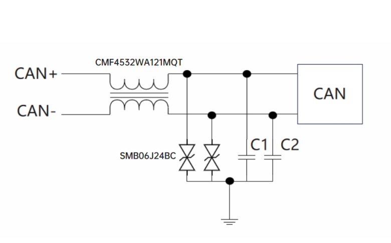
An RS-485 or CAN line carries a differential signal while being exposed to cable-induced common-mode voltage. It may also see ground offset, shorts, or a sustained fault. Before selecting a TVS, draw the relationship among the transceiver, termination, bias network, shield, signal reference, and chassis. That drawing determines where surge current is expected to return.
Record at least the following items for each candidate:
normal common-mode range and any continuous fault voltage;
TVS polarity, VRWM, leakage, and capacitance test conditions;
VC together with current and pulse waveform;
the transient tolerance of the transceiver or external network;
the physical distance from connector to TVS and from TVS to its return node;
differential waveform and communication result before and after the device is installed.
Placement is part of the clamp. If the surge current travels along a long PCB trace before it reaches the TVS, trace inductance can raise the voltage at the transceiver even when the catalog device is suitable.
High-speed ports put capacitance and layout near the top
USB, HDMI, MIPI, and other high-speed channels are sensitive to junction capacitance, package parasitics, pad geometry, and discontinuities. A low-capacitance ESD or TVS device is usually required, but the capacitance number must be read with frequency, bias, temperature, and typical-versus-maximum status.
A capacitance value measured at 0 V and 1 MHz does not replace insertion-loss, return-loss, or eye-diagram evidence at the target data rate. Save a baseline before fitting the protector, repeat the signal test after assembly, and then check function and leakage after ESD exposure. Recording only “the product did not reset” misses degraded links and latent leakage changes.
TVS diodes do not replace every other protection element
A TVS diode clamps a fast overvoltage. It does not automatically interrupt a sustained overcurrent. A fuse or electronic fuse handles continuous current risk. A MOV or gas discharge tube may be appropriate for a different energy and voltage range. A common-mode choke controls common-mode noise but is not a substitute for surge-energy handling.
The combination must be reviewed as an energy path. Check which element operates first, how much residual stress reaches the next stage, and where the current returns. Simply adding several protective parts around a connector does not prove coordination.
How to use the ASIM product information without over-claiming
ASIM publishes TVS series information with fields such as package, VRWM, VBR, IPP, VC, and leakage, together with data-sheet download routes for specific series. This is useful for building an initial candidate list by voltage, package, and pulse capability.
The approval step still belongs to the exact orderable part and the archived data-sheet revision. The waveform, temperature, polarity, test current, package, and production status must be carried into the project record. The defensible ASIM advantage is the ability to connect a searchable product matrix to part-level documentation and engineering verification. It is not a claim that one device fits every port.
A six-step application workflow
Describe the normal state. Record voltage, signal swing, bandwidth, polarity, and ambient range.
Describe the threat. Name the system test, waveform, source network, coupling point, polarity, and repetition.
Set the protection window. VRWM must tolerate normal operation; the actual clamped node must remain within the downstream limit.
Review non-ideal behavior. Include leakage, capacitance, dynamic resistance, package inductance, and thermal derating.
Place the device in the current path. Keep the exposed trace short and provide a low-inductance return that does not inject current into sensitive ground.
Verify the assembled product. Compare baseline and protected hardware under the same fixture, firmware, cable, and operating mode.
Frequently asked questions
Are TVS diodes used for ESD or for surge?
They can be used for both, but devices are optimized differently. High-speed interface protection emphasizes low capacitance and fast ESD clamping. Power-entry protection usually emphasizes surge waveform, current, thermal behavior, and the clamping window. Read the part-level data sheet rather than relying on the category name.
Can one 24 V TVS protect every 24 V interface?
No. Maximum continuous voltage, polarity, source impedance, pulse waveform, peak current, downstream tolerance, capacitance, package, and layout can all differ.
Does an IEC 61000-4-2 component rating guarantee a system pass?
No. System performance depends on the discharge point, enclosure, grounding, return path, operating mode, and acceptance criterion. Component data supports selection; the target product requires its own test.
Sources
Sources reviewed on September 23, 2026. Product status and data-sheet revisions can change; archive the revision used for each design decision.
OriginalAuthor: ASIM Technical Team|Publisher: Shenzhen ASIM Electronics Co., Ltd.
Published: 2026-09-23 Updated: 2026-09-23
Copyright: Copyright Shenzhen ASIM Electronics Co., Ltd. Cite the author and original URL when quoting or republishing.
Original URL: https://en.asim.com.cn/tvs-diode-applications-by-interface.html
 Previous