





 Submit


What issues need to be checked during EMC rectification?
 2026.07.22 00:00:00
 68
68





EMC remediation requires an examination across nine aspects: problem symptoms, test items, interference paths, schematics, PCB layout, cable interfaces, grounding methods, filtering components, and protection devices. Simply replacing a single component often fails to resolve all issues; a comprehensive remediation strategy involves first identifying the interference paths before determining necessary adjustments to components and structural design.
I. First, identify the specific test items.
EMC issues may arise from various tests, such as ESD, EFT, Surge, conducted emissions, radiated emissions, radiated immunity, BCI, or automotive load dump. The approach to remediation differs depending on the specific test item.
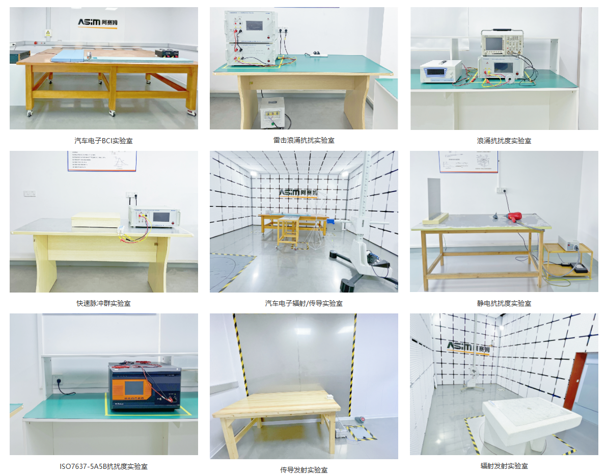
For example, when addressing ESD issues, prioritize examining discharge paths; for radiation issues, focus on high-speed signals, clocks, cables, and ground loops; and for surge issues, prioritize input protection and energy absorption.
II. Inspecting Interference Paths
It is necessary to determine whether the interference enters or is emitted via power lines, signal lines, the enclosure, cables, ground lines, or through radiated emissions. Misidentifying the path can easily turn the remediation process into a cycle of trial and error.
Components and configurations near interfaces—such as ESD protection, TVS diodes, common-mode chokes, ferrite beads, capacitors, and grounding schemes—are the areas most frequently examined during EMC remediation.
III. Schematic and PCB Review
The schematic review focuses on the completeness of protection components, parameter matching, and the soundness of filtering structures. The PCB review examines component placement, ground planes, return paths, trace lengths, partitioning, and cable exit points.
Many issues arise not from the absence of components, but from incorrect component placement, improper grounding, or energy paths that bypass the protection components.
IV. Asaim EMC Support
Asaim possesses an EMC laboratory and FAE technical support capabilities, enabling the company to provide customers with component selection, schematic evaluation, PCB rectification recommendations, testing and verification (including ESD, Surge, and EFT), and failure analysis support.
FAQs
Q: During EMC remediation, should the schematic or the PCB be modified first?
A: First, identify the problematic signal path; then, decide whether to modify the schematic, PCB, mechanical structure, or components.
Q: Can adding a ferrite bead solve EMI issues?
A: Not necessarily. A ferrite bead is just one possible measure; the choice depends on the frequency range, impedance, and return path.
Q: Are the remediation methods for ESD, Surge, and EFT the same?
A: No. They differ in terms of waveforms, energy levels, and coupling paths, requiring different component choices and layout strategies.
 Previous

Related News

2024.10.12
EMC testing Contents and Current Situation of Automotive Electronic products

2025.02.21
How to choose the best circuit protection devices in a circuit?
2026.06.22
ESD Diode vs TVS Diode: Which to Use and When
2026.07.10
What is the difference between SMD TVS and leaded (through-hole) TVS?
2026.07.13
What should be done if a USB interface fails ESD testing?
2026.07.15
What should be done if signal abnormalities occur after adding ESD protection to a MIPI interface?
2026.07.15
For what applications are SOD-323 packaged ESD diodes suitable?
2026.07.16
Common Issues Regarding ESD Protection for HDMI Interfaces
2026.07.16
How do I select the package for a TVS diode used with a 24V power supply?
2026.07.17
How should TVS diodes and common-mode inductors be configured for a CAN interface?


